A non-contact circular train control system and method

A train control system, non-contact technology, applied in the field of pantograph and catenary system, can solve the problems of material wear, decreased service performance of pantograph and catenary current receiving system, large mechanical impact of pantograph and catenary, etc. Requirements for ablative capacity and the effect of ensuring safe operation

Active Publication Date: 2021-03-30
SOUTHWEST JIAOTONG UNIV
View PDF5 Cites 0 Cited by
  • Summary
  • Abstract
  • Description
  • Claims
  • Application Information

AI Technical Summary

Problems solved by technology

[0004] Aiming at the above-mentioned deficiencies in the prior art, the present invention proposes a control system and method for a non-contact annular flow-receiving train, which is used to solve the problems in the prior art that the mechanical impact between the pantograph and catenary is large, the material wear is serious and the resulting pantograph and catenary The problem of rapid decline in the service performance of the flow receiving system

Method used


Image

  • A non-contact circular train control system and method
  • A non-contact circular train control system and method
  • A non-contact circular train control system and method

Examples


Embodiment Construction

[0043] The specific embodiments of the present invention are described below so that those skilled in the art can understand the present invention, but it should be clear that the present invention is not limited to the scope of the specific embodiments. For those of ordinary skill in the art, as long as various changes Within the spirit and scope of the present invention defined and determined by the appended claims, these changes are obvious, and all inventions and creations using the concept of the present invention are included in the protection list.

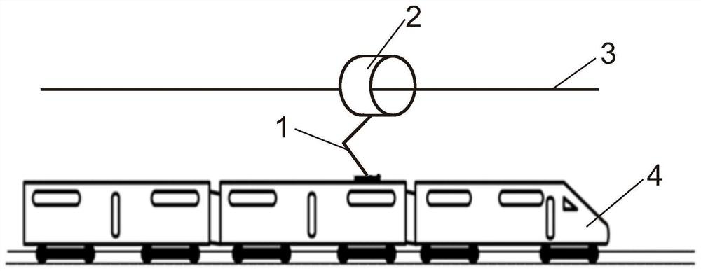
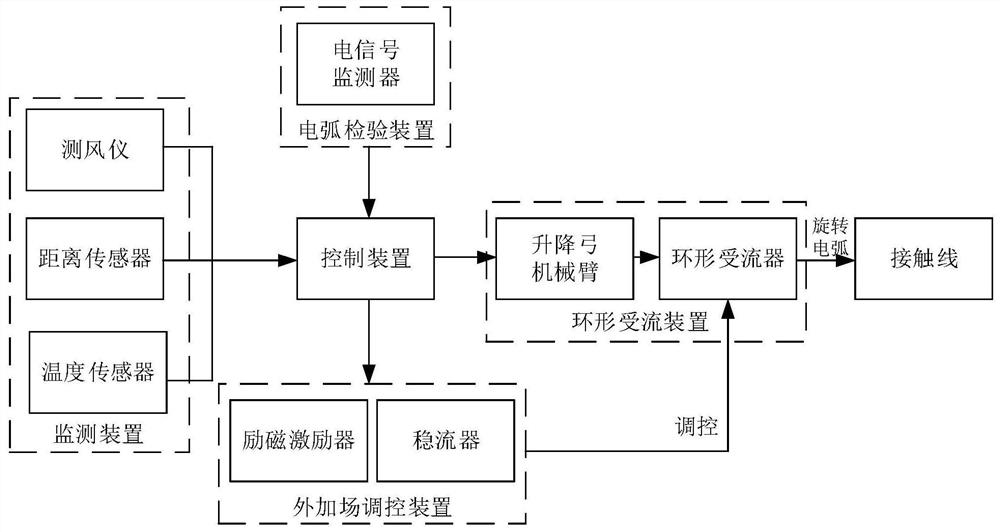
[0044] A non-contact circular flow train control system, such as figure 1 with figure 2 Commonly shown, including the control device, and the annular current receiving device, monitoring device, arc inspection device and external field regulation device that are all connected to the control device in communication, the control device is located inside the non-contact train 4, and the annular current receiving device includ...


PUM


Abstract

The invention discloses a control system and method for a non-contact annular current-receiving train, which includes a control device, and a ring-shaped current-receiving device, a monitoring device, an arc inspection device and an external field regulation device that are all communicatively connected to the control device. The control device is located at Inside the non-contact train, the annular current receiving device includes a fixedly connected lifting bow mechanical arm and a circular current collector. The lifting bow mechanical arm communicates with the control device. The device is electrically connected with the contact wire through the rotating arc, and the external field regulating device is electrically connected with the annular current collector. The invention changes the traditional sliding electric contact current receiving mode, and improves it to annular current receiving on the basis of non-contact current receiving, which not only avoids the rapid wear of the sliding plate and contact wire of contact current receiving and the intermittent pantograph-catenary off-line The disadvantages, but also to ensure a more stable annular flow.

Description

technical field [0001] The invention belongs to the technical field of pantograph-catenary systems, and in particular relates to a control system and method for a non-contact circular flow-receiving train. Background technique [0002] The pantograph-catenary system (pantograph-catenary slide / contact wire) is the only way for high-speed trains to obtain electric energy. Therefore, the quality of the pantograph-catenary relationship directly determines the quality of the flow. With the further increase of the speed of the high-speed train and the further increase of the heavy load, the pantograph-catenary vibration continues to increase, the frequency of mechanical shocks continues to increase, the mechanical damage of the pantograph occurs from time to time, and the wear of the pantograph slide is also very serious, requiring a large To replace the carbon slide plate, because high-speed trains have high requirements on the electrical and mechanical properties of the pantogra...

Claims


Application Information

Patent Timeline
Patent Type & Authority Patents(China)
IPC IPC(8): B60L5/00
CPCB60L5/005B60L2200/26
Inventor 高国强李成坤陈少昆魏文赋杨泽锋吴广宁
Owner SOUTHWEST JIAOTONG UNIV
Why Eureka
Try Eureka