Split type broadband steel rail damping vibration reduction noise reducer

A vibration and noise reduction, split-type technology, which is applied in the direction of tracks, roads, buildings, etc., can solve the problems of difficult continuous and synchronous arrangement of vibration and noise reduction devices, unfavorable vibration and noise reduction effects, uneven sleeper spacing, etc.

Pending Publication Date: 2019-08-09
陕西长美科技有限责任公司
View PDF0 Cites 7 Cited by
  • Summary
  • Abstract
  • Description
  • Claims
  • Application Information

AI Technical Summary

Problems solved by technology

The structure of the current common rail vibration and noise reducer is affected by the shape of the rail and the positions of sleepers and fasteners. During the laying process, the spacing is not uniform, so that the rail bottom shock absorber cannot be installed just at the center of the two sleepers, but the deformation of the rail at the center of the two sleepers is the largest, and the deviation from the center is not conducive to improving the effect of vibration and noise reduction. There are certain restrictions on the structural form of the waist and rail bottom shock absorbers

Method used


Image

  • Split type broadband steel rail damping vibration reduction noise reducer
  • Split type broadband steel rail damping vibration reduction noise reducer
  • Split type broadband steel rail damping vibration reduction noise reducer

Examples


Embodiment Construction

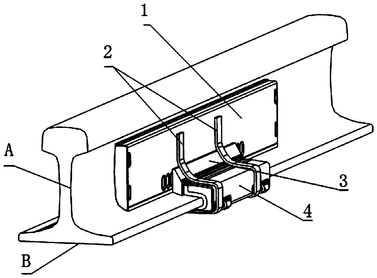
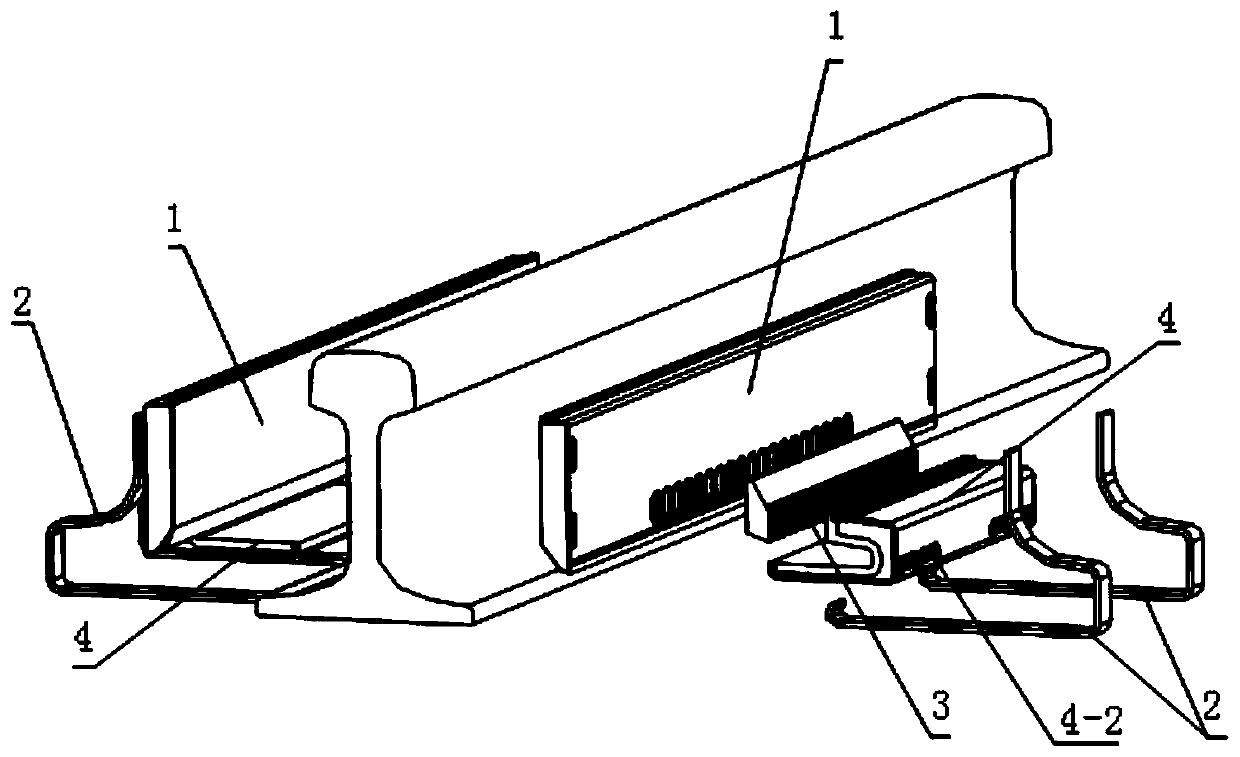
[0016] Such as figure 1 and figure 2 The rail damping vibration damping noise reducer shown includes a rail waist damping plate 1 , an intermediate adjustment block 3 , a rail bottom damping vibration absorber 4 and a snap spring 2 . The rail waist damping plate 1 is attached to the rail waist A to reduce vibration and noise on the rail waist. The entire rail is fully covered by several rail waist damping plates 1 spliced ​​together. The middle adjustment block 3 and the rail The waist damping plate 1 is in contact, the rail bottom damping shock absorber 4 is covered on the rail bottom B part and is in contact with the middle adjustment block 3, and the rail bottom damping shock absorber 4, the middle adjustment block 3 and the rail waist damping plate 1 Clamped on the rail. Wherein the middle adjusting block 3 and the rail bottom damping shock absorber 4 are only arranged between two sleepers and do not need to cover the whole section of the rail.

[0017] Such as image...


PUM


Abstract

The invention discloses a split type broadband steel rail damping vibration reduction noise reducer. The split type broadband steel rail damping vibration reduction noise reducer comprises a rail webdamping plate, which sticks to a rail web, and clamp springs; the split type broadband steel rail damping vibration reduction noise reducer further comprises a middle adjusting block and a rail bottomdamping vibration reducer; the middle adjusting block is in contact with the rail web damping plate; the bottom damping vibration reducer coats the rail bottom and is in contact with the middle adjusting block; one group of adjusting holes is formed in the contacting surface of the rail web damping plate and the middle adjusting block; limiting projections matched with the adjusting holes are arranged on the middle adjusting block; a sawtooth surface is arranged on the contacting surface of the middle adjusting block and the rail bottom damping vibration reducer; and a toothed surface matchedwith the sawtooth surface is arranged on the rail bottom damping vibration reducer. Through matched coarse adjusting of the limiting projections and the adjusting holes and through fine adjusting ofthe toothed surface and the sawtooth surface, it is guaranteed that the rail bottom damping vibration reducer is in a position between two sleepers; the adjusting mode is convenient and rapid; and moreover, the coordination between the limiting projections and the adjusting holes and the coordination between the sawtooth surface and the toothed surface can effectively prevent the rail bottom damping vibration reducer from jumping so that the vibration reduction effect is guaranteed.

Description

technical field [0001] The invention relates to a rail damping and noise reducer, in particular to a split type rail damping and noise reducer. Background technique [0002] Vibration and noise are recognized as the most widely affected public hazards, and they are also a problem that needs to be solved urgently in the development of rail transit in recent years. The structure of the current common rail vibration and noise reducer is affected by the shape of the rail and the positions of sleepers and fasteners. During the laying process, the spacing is not uniform, so that the rail bottom shock absorber cannot be installed just at the center of the two sleepers, but the deformation of the rail at the center of the two sleepers is the largest, and the deviation from the center is not conducive to improving the effect of vibration and noise reduction. The structural forms of the waist and rail bottom shock absorbers have certain restrictions. Contents of the invention [0...

Claims


Application Information

Patent Timeline
Patent Type & Authority Applications(China)
IPC IPC(8): E01B19/00
CPCE01B19/003
Inventor 张法明侯煜李晓云王红英陈刚杨铁梅李强郭俊峰
Owner 陕西长美科技有限责任公司
Why Eureka
Try Eureka