Al technical title is built by PatSnap Al team. It summarizes the technical point description of the patent document.
A well-type furnace and furnace door technology, which is applied in the direction of furnaces, furnace doors, furnace components, etc., can solve the problems of not being able to rotate while rising, poor stability, and safety, so as to facilitate operation, solve safety problems, The effect of increased safety
Pending Publication Date: 2019-08-09
HENAN TIANLI THERMOTECHNICAL EQUIP CO LTD
View PDF1 Cites 2 Cited by
Summary
Abstract
Description
Claims
Application Information
AI Technical Summary
This helps you quickly interpret patents by identifying the three key elements:
Problems solved by technology
Method used
Benefits of technology
Problems solved by technology
[0008] The purpose of the present invention is to provide a hoisting device for a well-type furnace, which solves the problems that the hoisting equipment for a well-type furnace at the present stage cannot rotate while rising when in use, has poor stability, and has potential safety hazards during use.
Method used
Image
Click on the blue label to locate the original text in one second.
Reading with bidirectional positioning of images and text.
Examples
Embodiment Construction
[0024] The following will clearly and completely describe the technical solutions in the embodiments of the present invention with reference to the accompanying drawings in the embodiments of the present invention. Obviously, the described embodiments are only some, not all, embodiments of the present invention. Based on the embodiments of the present invention, all other embodiments obtained by persons of ordinary skill in the art without making creative efforts belong to the protection scope of the present invention.
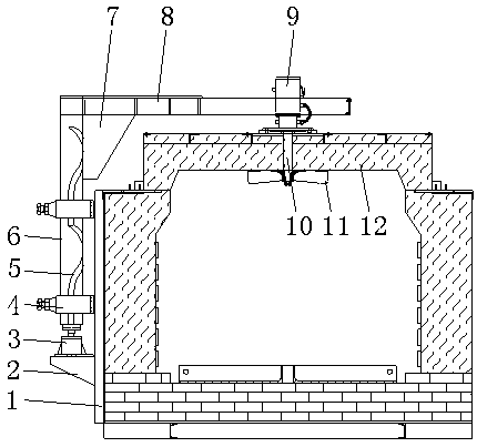
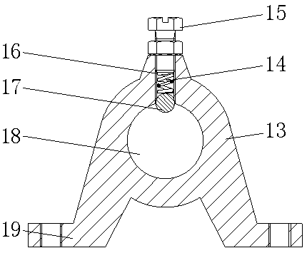
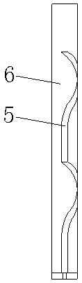
[0025] Such as Figure 1-3 As shown, an embodiment provided by the present invention: a hoisting device for a well-type furnace, including a wall 1 and a furnace door 12, a motor 3 is fixed on the outer wall of the wall 1 through a mounting seat 2, and the output end of the motor 3 rotates A shaft 6 is connected, and the outer wall of the shaft 6 is sequentially sleeved with a limit seat 4, the limit seat 4 is installed on the outer end of the wall 1, and the ...
PUM
Abstract
The invention discloses a pit type furnace lifting device. The pit type furnace lifting device comprises a wall body and a furnace door, a motor is fixed on the outer wall of the wall body through a mounting seat, the output end of the motor is rotationally connected with a shaft rod, the outer wall of the shaft rod is sequentially sleeved with limiting seats, the limiting seats are arranged at the outer end of the wall body, a top beam is fixed to the top end of the shaft rod through a reinforcing plate, a hydraulic cylinder is arranged on the top beam, a control rod is fixed at the output end of the bottom of the hydraulic cylinder, a lifting table is arranged at the lower end of the control rod, the furnace door is fixed on the lifting table, and each limiting seat internally comprisesa limiting seat body and a base. According to the pit type furnace lifting device, the motor, the limiting seats, a spiral groove, the shaft rod, the reinforcing plate, the top beam, the hydraulic cylinder, the lifting table, a spring, a limiting cavity, a ball and a limiting through hole are arranged, so that the problems that when a pit type furnace lifting device is used at the present stage, lifting and rotating can not be performed at the same time, the stability is poor, and potential safety hazards exist during use are solved.
Description
technical field [0001] The invention relates to the technical field of boiler equipment, in particular to a well type furnace lifting device. Background technique [0002] At present, the pit furnace is a periodic operation furnace, which is suitable for heat treatment of rods and long shaft parts. The structure of the well-type furnace is: the furnace body is a cylindrical deep well, and the workpiece is vertically loaded into the furnace by a special crane for heating. The fuel used is usually gas and oil. When electricity is used as the heat source, it is called a well-type resistance furnace. The pit furnace is generally placed below the ground level of the workshop, and some are placed above the ground level, or half above and below the ground level. The names of well-type furnaces include: forced convection well-type furnace, natural convection well-type furnace, well-type gas carburizing furnace, etc. When the boiler is in use, the furnace door part needs to be fre...
Claims
Application Information
Patent Timeline
Application Date:The date an application was filed.
Publication Date:The date a patent or application was officially published.
First Publication Date:The earliest publication date of a patent with the same application number.
Issue Date:Publication date of the patent grant document.
PCT Entry Date:The Entry date of PCT National Phase.
Estimated Expiry Date:The statutory expiry date of a patent right according to the Patent Law, and it is the longest term of protection that the patent right can achieve without the termination of the patent right due to other reasons(Term extension factor has been taken into account ).
Invalid Date:Actual expiry date is based on effective date or publication date of legal transaction data of invalid patent.