Novel material taking and placing mechanical arm for glass fine carving machine

A technology of engraving machines and manipulators, applied in manipulators, program-controlled manipulators, engraving, etc., can solve the problems of reducing the service life of the screw guide rails of engraving machines, leaving residues on the processing table, affecting the smooth progress of work, etc., to achieve The effects of cleaning the mold surface, reducing weight and volume, and optimizing the structure

Pending Publication Date: 2019-09-10
SHENZHEN YANCHUANG PRECISION EQUIP MACHINERY
View PDF0 Cites 5 Cited by
  • Summary
  • Abstract
  • Description
  • Claims
  • Application Information

AI Technical Summary

Problems solved by technology

[0003] There is a new type of pick-and-place manipulator for glass engraving machines. There are certain disadvantages in use. First, the existing manipulator is too heavy and bulky, which will reduce the service life of the screw guide rail of the engraving machine. At the same time, in the process of processing glass, the residue after processing may remain on the processing table, which will affect the smooth progress of the work. Therefore, we propose a new type of pick-and-place manipulator for glass engraving machines

Method used


Image

  • Novel material taking and placing mechanical arm for glass fine carving machine
  • Novel material taking and placing mechanical arm for glass fine carving machine
  • Novel material taking and placing mechanical arm for glass fine carving machine

Examples


Embodiment Construction

[0032] The following will clearly and completely describe the technical solutions in the embodiments of the present invention with reference to the accompanying drawings in the embodiments of the present invention. Obviously, the described embodiments are only some of the embodiments of the present invention, not all of them.

[0033] In describing the present invention, it should be understood that the terms "upper", "lower", "front", "rear", "left", "right", "top", "bottom", "inner", " The orientation or positional relationship indicated by "outside", etc. is based on the orientation or positional relationship shown in the drawings, and is only for the convenience of describing the present invention and simplifying the description, rather than indicating or implying that the referred device or element must have a specific orientation, so as to Specific orientation configurations and operations, therefore, are not to be construed as limitations on the invention.

[0034] Such...


PUM


Abstract

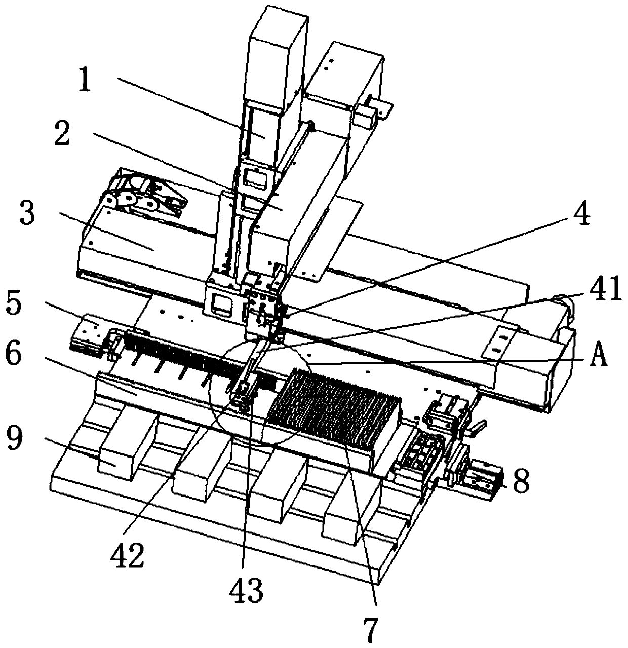
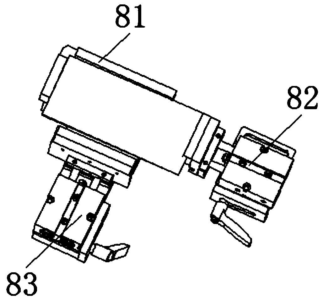
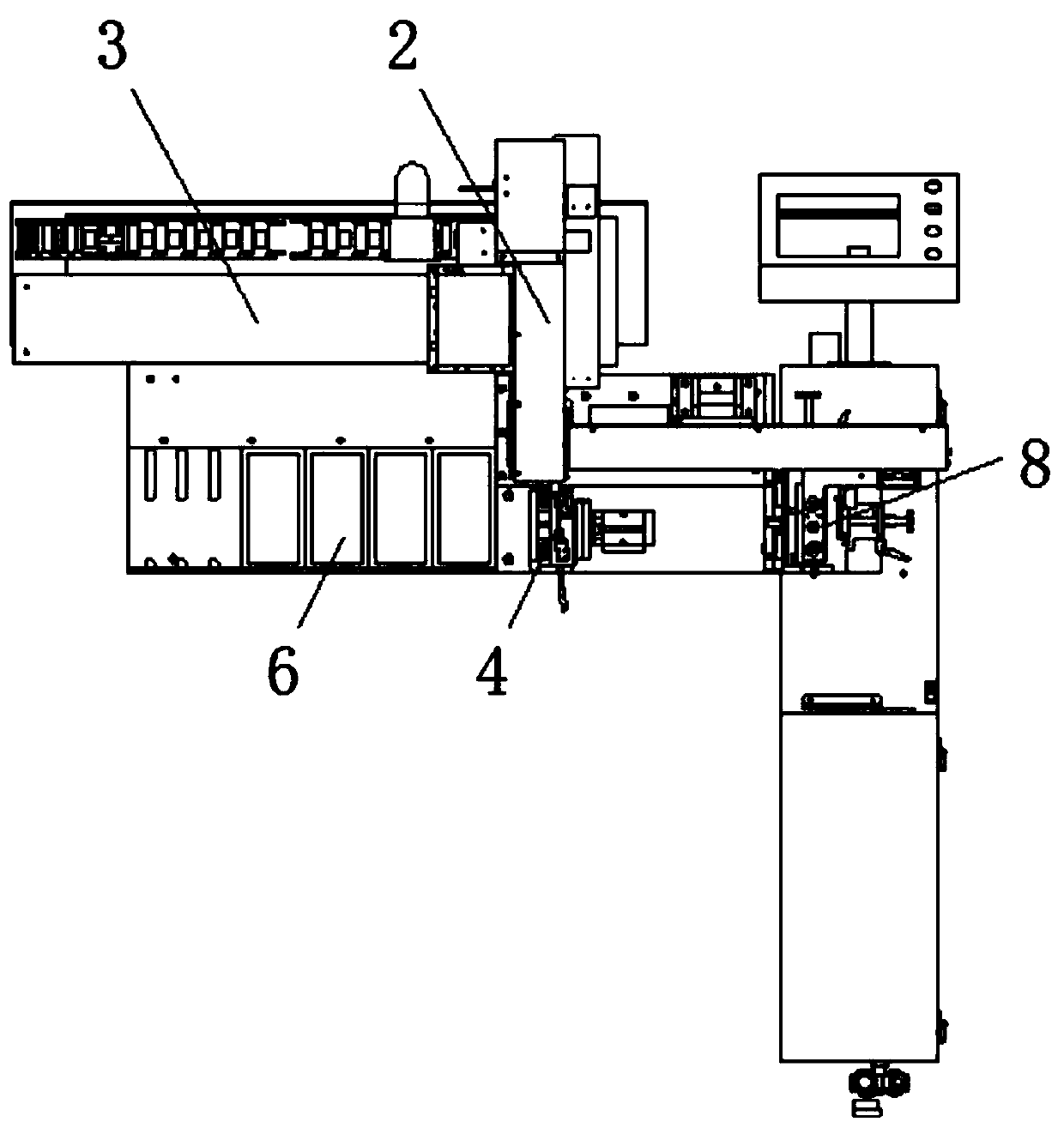
The invention discloses a novel material taking and placing mechanical arm for a glass fine carving machine. The novel material taking and placing mechanical arm comprises a module assembly, a basketpositioning mechanism, a basket assembly, a glass positioning mechanism and a machining mold, wherein the module assembly and the machining mold are arranged on the front side and the rear side of thebasket assembly, and the basket positioning mechanism and the glass positioning mechanism are respectively arranged at the left end and the right end of the basket assembly; and the module assembly comprises a Z-axis module, a Y-axis module and an X-axis module, and one end of the Y-axis module is provided with a rotating mechanism. According to the novel material taking and placing mechanical arm, three modules are used for realizing the X-axis and Y-axis of the mechanical arm, the motion in the Z-axis three-dimensional direction is replaced, manual feeding and discharging are replaced, andpersonnel can be saved; the rotating mechanism is arranged in front of the Y-axis module, so that a sucker can rotate by 90 degrees; and by utilizing the adsorbability of the sucker, the material taking and placing can be conveniently carried out, the structure is optimized, the weight and the size of the mechanical arm are reduced, and the running speed and the efficiency of the device are improved.

Description

technical field [0001] The invention relates to the field of glass, in particular to a novel pick-and-discharge manipulator for glass engraving machines. Background technique [0002] Glass is an amorphous inorganic non-metallic material, generally made of various inorganic minerals (such as quartz sand, borax, boric acid, barite, barium carbonate, limestone, feldspar, soda ash, etc.) Yes, its main components are silicon dioxide and other oxides. [0003] There is a new type of pick-and-place manipulator for glass engraving machines. There are certain disadvantages in use. First, the existing manipulator is too heavy and bulky, which will reduce the service life of the screw guide rail of the engraving machine. , At the same time, in the process of processing glass, the residue after processing may remain on the processing table, which will affect the smooth progress of the work. Therefore, we propose a new type of pick-and-place manipulator for glass engraving machines. ...

Claims


Application Information

Patent Timeline
Patent Type & Authority Applications(China)
IPC IPC(8): B44B1/06B44B3/06B25J9/02B25J15/06
CPCB25J9/023B25J15/065B25J15/0683B44B1/06B44B3/06
Inventor 甄强余冲冲
Owner SHENZHEN YANCHUANG PRECISION EQUIP MACHINERY
Why Eureka
Try Eureka