[0047] In order to make the objectives, technical solutions, and advantages of the embodiments of the present invention clearer and clearer, the following will clearly illustrate the spirit of the content of the present invention with the accompanying drawings and detailed descriptions. Any person skilled in the art will understand the embodiments of the present invention. However, the technology taught in the content of the present invention can be changed and modified without departing from the spirit and scope of the content of the present invention.
[0048] The exemplary embodiments of the present invention and their descriptions are used to explain the present invention, but not as a limitation to the present invention. In addition, elements/components with the same or similar numbers used in the drawings and the embodiments are used to represent the same or similar parts.
[0049] Regarding the "first", "second", etc. used in this text, they do not specifically refer to the order or sequence, nor are they used to limit the present invention. They are only used to distinguish elements or operations described in the same technical terms. .
[0050] With regard to the directional terms used in this text, for example: up, down, left, right, front or back, etc., only the directions with reference to the drawings are used. Therefore, the directional terms used are used to illustrate and not to limit this creation.
[0051] As used herein, "including", "including", "having", "containing", etc., are all open terms, which means including but not limited to.
[0052] Regarding the "and/or" used herein, it includes any or all combinations of the above-mentioned things.
[0053] Regarding the terms "approximately" and "about" used in this article, they are used to modify any amount or error that can be slightly changed, but these slight changes or errors will not change its essence. Generally speaking, the range of slight changes or errors modified by such terms may be 20% in some embodiments, 10% in some embodiments, 5% in some embodiments, or other values. Those skilled in the art should understand that the aforementioned values can be adjusted according to actual needs and are not limited thereto.
[0054] Some terms used to describe this application will be discussed below or elsewhere in this specification to provide those skilled in the art with additional guidance on the description of this application.
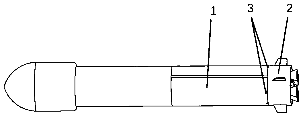
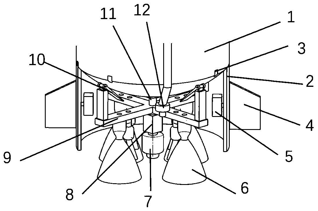
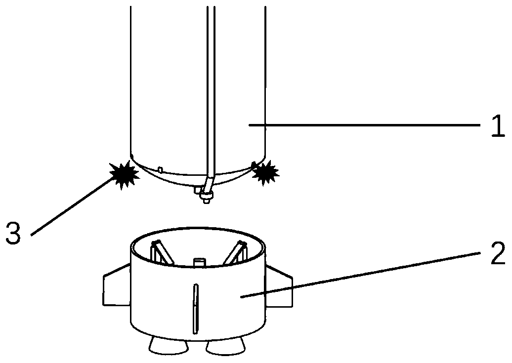
[0055] See figure 1 with figure 2 As shown, the embodiment of the present invention provides a liquid rocket, which includes a rocket sub-stage 1, and also includes a powered tail section 2, a parachute bag 7 and an explosive separation structure; wherein the power tail section 2 is connected by an explosive separation structure The first stage 1 of the rocket, the explosion separation surface is located between the bottom of the storage tank of the first stage and the power tail section 2. The parachute bag 7 is arranged in the power tail section 2; after the first stage 1 is separated, the explosion separation The structure is detonated, so that the power tail section 2 is separated from the bottom of the tank along the explosion separation surface, and the parachute bag 7 is opened to reduce the descent speed of the power tail section 2.
[0056] Specifically: the liquid rocket is composed of rocket first sub-stage 1, power tail compartment 2, parachute bag 7 and explosive separation structure. The bottom of the storage tank of rocket first sub-stage 1 and power tail compartment 2 are connected by the explosive separation structure. After the first sub-stage 1 of the rocket is separated, the explosive separation structure is detonated, so that the power tail section 2 is separated from the bottom of the tank along the explosion separation surface. At this time, the parachute bag 7 on the power tail section 2 is opened, and the power tail section 2 is lowered. The descent speed ensures the safe landing of the power tail section 2 and completes the recovery of the power tail section 2. This structure is convenient to control, safe and reliable, and can save costs. It can be used for maintenance, testing and cleaning of the power tail section 2 and can be repeatedly used .
[0057] It is worth mentioning that such as figure 1 , image 3 , Picture 10 , Picture 11 As shown, the explosion separation structure includes a separation explosion bolt 2 and a holder 23. The holder 23 includes a first part fixedly connected to the outer shell of the power tail compartment 2 (ie Picture 11 The upper part of the holder 23 shown in) and the second part fixedly connected to the adjacent shell of the first sub-stage 1 of the rocket and the outer shell of the power tail section 2 (ie Picture 11 As shown in the lower part of the holder 23), the separated explosive bolt 2 fixes the first part and the second part to each other by penetrating the first part and the second part. By detonating the separating explosive bolt 3, the first part and the second part are separated, and the separation of the power tail section 2 is further completed, which is beneficial to the recovery of the subsequent power tail section 2. It is worth mentioning that, in order to facilitate the fixing of the separation explosion bolt 2, the parts of the separation explosion bolt 2 respectively protruding from the opposite sides of the first part and the second part are fixed by nuts.
[0058] It should be noted that such as figure 2 As shown, the parachute bag 7 is fixed on the power tail section 2 by a parachute fixing bracket 8.
[0059] In this embodiment, as shown in the figure figure 2 , image 3 , Image 6 , Figure 7 , Figure 8 , Picture 9 with Figure 14 As shown, in order to make the landing of the power tail section 2 more stable, a landing leg 10 is provided on the power tail section 2. The landing leg is connected to the power tail section 2 through the engine mounting frame 9, and the landing leg 10 is located on the upper part of the engine mounting frame 9 (ie, the side of the engine mounting frame opposite to the side where the engine is installed). It should be noted that, in order to facilitate the opening of the landing leg 10, the landing leg 10 is composed of a support base 16, a connecting shaft 17, a spring 18, and a floor 19. One side of the support base 16 is provided with a protrusion 21 and the other The side is connected to the engine mounting frame 9, the boss 21 is provided with a through hole 22, one end of the floor contact 19 is provided with an open channel 20, and the connecting shaft 17 penetrates the through hole 22 and the open channel 20 to connect the floor contact 19 with the support base 16. Therefore, the floor contact 19 is configured to rotate around the connecting shaft 17, and the spring 18 is sleeved on the connecting shaft 17 to assist the floor contact 19 to open. In order to fix the convex column 27 conveniently, the shape of the convex column 27 is a cylindrical structure. It should be mentioned that in order to improve the pressure bearing of the convex portion 21, the convex portion 21 is designed to resemble a rectangular parallelepiped structure.
[0060] figure 1 with Figure 8 In order to facilitate the opening of the floor contact 19, the thickness of the end of the floor contact 19 away from the connecting shaft 17 is greater than the thickness of the end close to the connecting shaft 19. Since the thickness of the end of the floor contact 19 away from the connecting shaft 17 is greater than the thickness of the end close to the end of the connecting shaft 17, the center of gravity of the floor contact 19 and the center of the support base are no longer on the same straight line, and the center of gravity is located on the side away from the power tail compartment 2. When the power tail section is overturned (the engine nozzle is upward), it is subjected to gravity in the vertical direction, so that the floor contact 19 rotates downward with the connecting shaft 17 as the center, and forms a certain angle with the support seat 16. According to the force analysis, this structure decomposes the gravity of the entire power tail section, reduces the force of the power tail section 2 in the vertical direction, and helps to make the power tail section 2 landing smoothly. In particular, this implementation In the manner, the shape of the touch floor 19 is similar to a trapezoidal structure.
[0061] It is worth mentioning that such as Figure 7 with Figure 8 As shown, in this embodiment, in order to make the protrusion 21 and the support base 16 more closely connected, the two are welded and connected. In this embodiment, the protrusion 21 and the support base 16 are mutually independent components for description, and in the actual application process, in order to make the protrusion 21 and the support base 16 more tightly and firmly connected, the two It is designed to be integrally formed, and the process is not explained here.
[0062] It should be pointed out that such as Image 6 As shown, the landing leg 10 can be changed due to the landing environment. When the power tail module 2 is landed on the sea, the landing leg 10 can be changed to a floating cut. When landing in the desert, the power tail module 2 can be installed without landing. The outrigger 10, here, does not describe the process one by one.
[0063] In this embodiment, as figure 2 As shown, the power tail section 2 may include a shell, multiple parallel engines 6, an engine mounting frame 9 and an adjustable tail device. The multiple parallel engines 6 and the engine mounting frame 9 are all located inside the shell, the engine mounting frame 9 is located in the parachute bag 7, the parachute fixing bracket 8 and the upper part of the multiple parallel engines 6 (when the rocket is upright), namely The parachute bag 7, the parachute fixing bracket 8 and the multiple parallel engines 6 are all arranged on the same side of the engine mounting frame 9. The two ends of the parachute fixing bracket 8 are respectively connected to the parachute bag 7 and the engine mounting bracket 9. For example, the parachute fixing bracket 8 can be located on the center line of the engine mounting frame 9 and close to the side of the multiple parallel engines 6, one end of the multiple parallel engines 6 is connected to the engine mounting frame 9, and the nozzle faces away from the engine frame 9 side.
[0064] For example, such as figure 2 with Figure 5 As shown, the landing leg 10 may be a pop-up leg, one end of which is connected to the engine mounting frame 9 and located on the side of the engine mounting frame 9 away from the parachute bag 7. The parachute bag 7 is electrically connected with a first controller, and the first controller is used for detecting the attitude of the power tail section and controlling the opening of the parachute bag 7. The adjustable tail device includes an adjustable tail 4 and a second controller 5, and the second controller 5 is connected to the adjustable tail device 4 through an electrical wire. The adjustable tail 4 is partially located on the outer side of the shell of the power tail section, and the second controller 5 is located on the inner side of the shell. For example, the second controller 5 may be a tail servo controller for adjusting the posture of the adjustable tail 4. For example, the first controller can set the inclination angle of the power tail section, and the second controller 5 adjusts the angle of the adjustable tail 4 according to the inclination angle, so that after the angle of the power tail section reaches the set value, the first A controller controls, for example, the opening of the parachute.
[0065] For example, such as image 3 with Figure 4 As shown, when the power tail section 2 is not equipped with an adjustable tail, the first controller can detect the falling attitude of the power tail section in real time, and when the axis of the power tail section 2 is at a certain angle to the direction of gravity, Control the parachute to open. After the decelerating parachute 13 is opened, the falling speed of the decelerating parachute 13 under the action of the airflow is much slower than the falling speed of the powered tail section 2, so the decelerating parachute 13 is quickly located above the powered tail section, and acts on the power along the direction of gravity. The tail compartment 2 decelerates.
[0066] Special attention is needed, such as figure 2 , Figure 8 with Figure 13 As shown, in order to facilitate the adjustment of the position of the landing leg 10, a plurality of fixing holes 26 may be provided in the engine mounting frame 9 to facilitate the fixing of the raised column 27, so that the landing leg 10 is firmly fixed.
[0067] Such as figure 2 As shown, in order to reduce the cost, the oxidizer main line separation valve 11 and the fuel main line separation valve 12 are designed in the shell of the power tail section, so that they can be recycled together when the power tail section is recovered to realize reuse. cut costs.
[0068] Special, such as figure 2 As shown, in the recovery process of the power tail section 2, in order to facilitate the location of the power tail section 2, a navigation locator can be provided in the housing, so that through the communication between the navigation locator and the ground signal receiver, Real-time monitoring of the position change of the power tail section.
[0069] In this embodiment, as Figure 5 with Image 6 As shown, the parachute bag 7 includes a deceleration parachute 13 and a main parachute 14. The deceleration parachute 13 may be located outside the main parachute 14, and the two may not interfere with each other when opened. For example, the first controller can obtain the attitude of the power tail section 2 through sensors. When the axis direction of the power tail section 2 is at a certain angle with the direction of gravity or the engine nozzle faces the side away from the ground, the first controller controls the deceleration The umbrella opens. The deceleration parachute 13 is used to adjust the posture of the power tail section 2 and to decelerate, so that the power tail section 2 is in a vertical state. When the engine of the power tail section 2 faces away from the ground and is perpendicular to the ground, the first controller controls the main parachute 14 to open. The main parachute 14 is used to decelerate the power tail section 2 to ensure the recovery of the entire device.
[0070] In addition, it is worth mentioning that such as figure 2 , Figure 5 with Image 6 As shown, in the actual application process, the controller can control the deceleration parachute 13 to open when the extension line of the engine axis of the power tail compartment 2 is greater than 45 degrees with the ground. Due to gravity and air friction, when the deceleration parachute 13 is opened The landing speed is less than the landing speed of the power tail section 2. When the engine of the power tail section 2 faces away from the ground and is substantially perpendicular to the ground, the main parachute 14 is opened to ensure the recovery of the entire device.
[0071] Such as figure 1 with Picture 12 As shown, in order to ensure the safety of the recovery of the power tail section 2, a landing platform 15 may be installed at the landing place of the power tail section 2. In this embodiment, the shape of the landing platform 15 may be a cube structure. In the actual application process, the shape of the landing platform 15 may also be rectangular, round, diamond, etc., which will not be described here. In particular, it should be noted that, in order to reduce the pressure between the power tail section 2 and the landing platform 15, a colloid layer 25 may be provided on the upper surface of the landing platform 15. The colloid layer 25 acts as a buffer during the landing of the power tail section, thereby ensuring the safety of the power tail section 2 landing. Further, in order to avoid displacement and movement of the colloid layer 25, the colloid 25 and the landing platform 15 are in close contact with each other, and the two are adhesively connected.
[0072] To facilitate separation, such as image 3 The multiple explosive separation structures are evenly arranged in the circumferential direction where the power tail section 2 is connected to the first sub-stage 1 of the rocket.
[0073] It should be noted that such as figure 2 The power tail section 2 includes an engine frame 9 and a parachute fixing bracket 8. One end of the parachute fixing bracket 8 is fixedly connected to the engine frame 9 near the engine nozzle side, and the other end is used for setting a parachute pack 7.
[0074] In this embodiment, it is worth mentioning that the connection methods include threaded connection, welding, riveting, etc., which are not described in detail here.
[0075] The above are only illustrative specific embodiments of the present invention. Without departing from the concept and principle of the present invention, any equivalent changes and modifications made by those skilled in the art shall fall within the protection scope of the present invention. .