
Thin-walled part micro-vibration measurement method and system based on motion amplification optical flow tracking

A vibration measurement and optical flow tracking technology, which is used in measurement devices, measurement of ultrasonic/sonic/infrasonic waves, image data processing, etc. Convenient, high spatial resolution effects

Active Publication Date: 2019-08-09
HUNAN UNIV OF SCI & TECH
View PDF8 Cites 17 Cited by
  • Summary
  • Abstract
  • Description
  • Claims
  • Application Information

AI Technical Summary

Problems solved by technology

Optical measurement technology has the advantages of high precision, high sensitivity, non-contact, can be used in flammable and explosive harsh environments, and has no damage to the surface. It has become the main means of high-precision vibration measurement, such as laser vibration measurement and visual vibration measurement. Such methods can independently and objectively complete the measurement of the measured object. Among them, the displacement measured by the laser vibration measurement method can be as small as several microns, and the measurement accuracy can reach tens of nanometers, but the spatial resolution is low; the existing visual measurement method has high spatial resolution. Resolution, non-contact, simple operation, etc., but the measurement accuracy is limited
According to the latest research, the visual vibration measurement platform based on binocular stereo vision can measure the displacement of 0.1mm, but the measurement error reaches 0.028mm, and the diagonal field of view is only 0.2m
At the same time, for the two methods, due to the small vibration amplitude, the naked eye cannot judge and select the appropriate measurement position. To obtain the required measurement position points such as the data of the maximum amplitude position, it is necessary to measure the position of the measured object differently. With a large number of measurements, it is clear that this method is difficult to implement
[0004] To sum up, the existing vibration measurement technology cannot effectively solve the measurement problem of micro-amplitude vibration.

Method used


Image

  • Thin-walled part micro-vibration measurement method and system based on motion amplification optical flow tracking
  • Thin-walled part micro-vibration measurement method and system based on motion amplification optical flow tracking
  • Thin-walled part micro-vibration measurement method and system based on motion amplification optical flow tracking

Examples


Embodiment 1

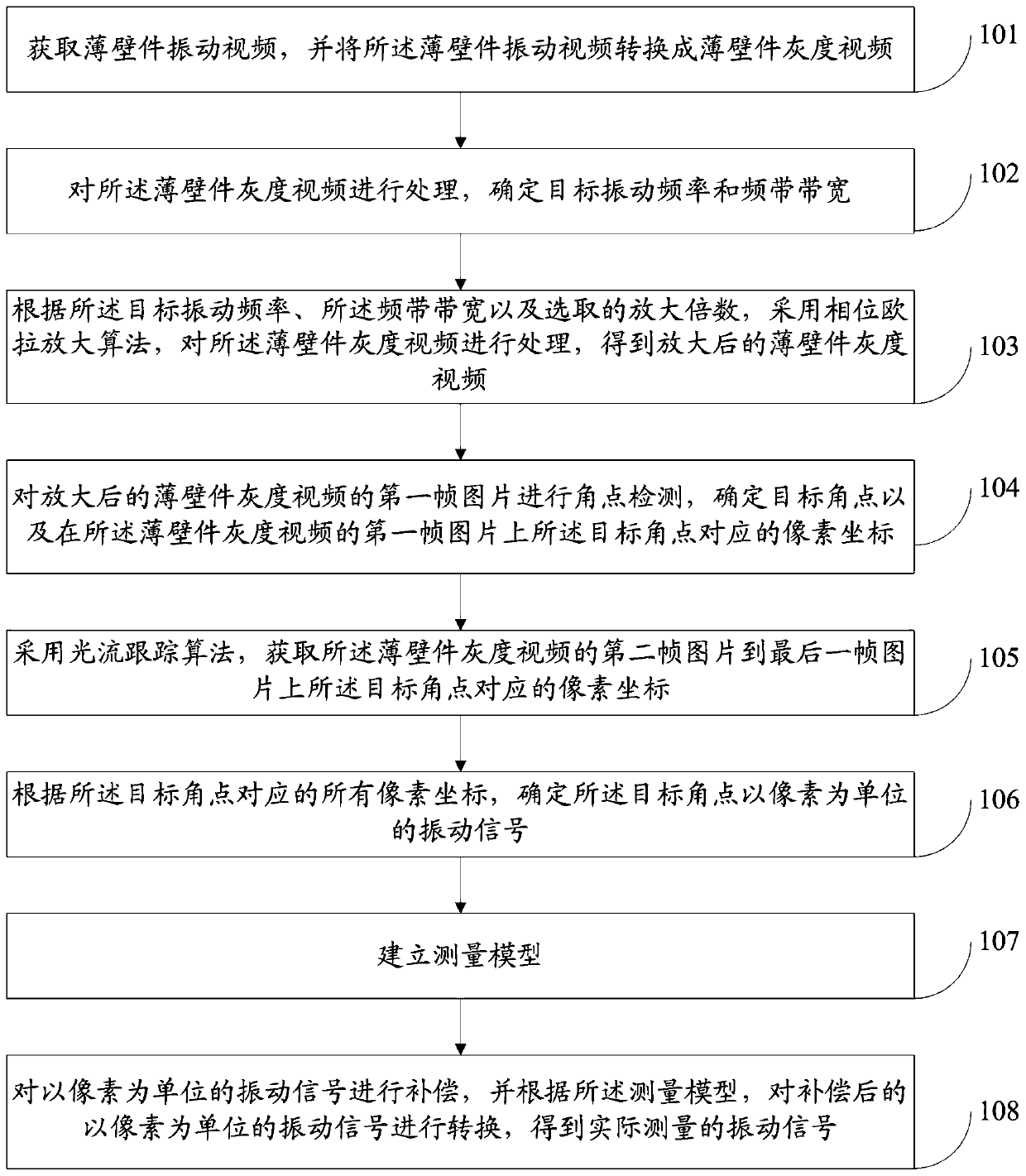
[0060] Such as figure 1 As shown, the method for measuring the micro-vibration of thin-walled parts based on motion amplification optical flow tracking provided by this embodiment includes the following steps:

[0061] Step 101: Obtain a thin-walled part vibration video, and convert the thin-walled part vibration video into a thin-walled part grayscale video.

[0062] Step 102: Process the gray-scale video of the thin-walled part to determine the target vibration frequency and frequency bandwidth.

[0063] Step 103: According to the target vibration frequency, the frequency band width and the selected magnification factor, the phase Euler amplification algorithm is used to process the gray-scale video of the thin-walled part to obtain the enlarged gray-scale video of the thin-walled part.

[0064] Step 104: Perform corner detection on the first frame picture of the enlarged grayscale video of the thin-walled part, and determine the target corner point and the corner point cor...

Embodiment 2

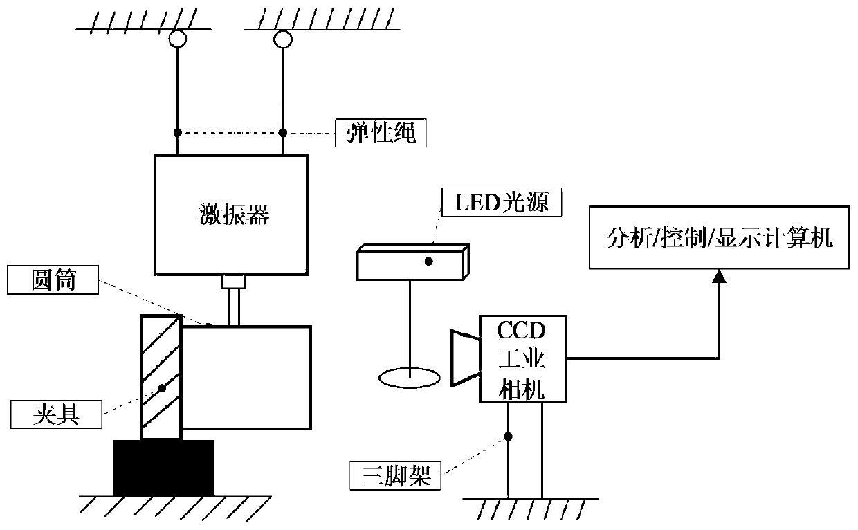
[0082] Such as Figure 2-3 As shown, the thin-walled micro-vibration measurement device based on motion amplification and optical flow tracking of the present invention includes a tripod, a CCD industrial camera, a fixture, a vibrator and its control device, an LED light source, a thin-walled cylinder to be tested, a computer, and an elastic rope . One end of the thin-walled cylinder to be tested is fixed with a fixture, and multiple reflective feature points are arranged at equal intervals at the other end. The vibrator is suspended directly above the thin-walled cylinder to be tested with an elastic rope, and connected to the thin-walled cylinder to be tested through a rod. The CCD industrial camera is fixed horizontally in front of the end face of the thin-walled cylinder to be measured through a tripod, the lens is facing the end face, and the CCD industrial camera is connected to the control device through a data cable. The LED light source is set in front of the end fac...

Embodiment 3

[0101] Such as Figure 4 As shown, this embodiment provides a thin-walled micro-vibration measurement system based on motion amplification optical flow tracking, including:

[0102] Thin-wall grayscale video conversion module 100, configured to acquire thin-wall vibration video, and convert the thin-wall vibration video into thin-wall grayscale video;

[0103] The target vibration frequency and frequency band width determination module 200 is used to process the gray-scale video of the thin-walled part to determine the target vibration frequency and frequency band width;

[0104]The thin-walled part gray-scale video amplification module 300 is used to process the gray-scale video of the thin-walled part by using the phase Euler amplification algorithm according to the target vibration frequency, the frequency band width and the selected magnification factor to obtain the enlarged Grayscale video of thin-walled parts after;


PUM


Abstract

The invention discloses a thin-walled part micro-vibration measurement method and system based on motion amplification optical flow tracking, and relates to the technical field of thin-walled part micro-vibration measurement. The method comprises the following steps of obtaining a target vibration frequency through the brightness change; processing a gray level image sequence through a phase Eulermethod and amplifying the vibration amplitude; processing a video subjected to motion amplification by adopting an optical flow tracking algorithm, extracting a vibration signal of a target angular point taking the pixel as a unit, and compensating the attenuation; and establishing a measurement mathematical model and converting the measurement mathematical model into a vibration signal of an actual unit. According to the thin-walled part micro-vibration measurement method based on the motion amplification optical flow tracking provided by the invention, a phase Euler amplification method andan optical flow tracking method are combined, so that the problem that the micro-vibration of a thin-walled part cannot be measured is effectively solved, and the method has the advantages of being convenient to operate, high in spatial resolution, non-contact, visual in micro-vibrations and the like.

Description

technical field [0001] The invention relates to the technical field of micro-amplitude vibration measurement of thin-walled parts, in particular to a method and system for measuring micro-amplitude vibration of thin-walled parts based on motion amplification optical flow tracking. Background technique [0002] The measurement and research of tiny vibration signals are of great significance in both military and civilian applications. This kind of vibration signal generally exists in the vibration of thin-walled parts of aero-engines. According to relevant studies, the vibration amplitude of thin-walled parts of aero-engines is between tens of microns and hundreds of microns. Since thin-walled parts are often used as the main structural form in aero-engines, accurate and efficient acquisition of vibration signals of aero-engines' thin-walled parts is of great significance for research on vibration characteristics analysis, vibration reduction optimization design, and structur...

Claims


Application Information

Patent Timeline
Patent Type & Authority Applications(China)
IPC IPC(8): G01H9/00
CPCG01H9/00G06T2207/10016G06T2207/20016G06T2207/30164G06T7/207
Inventor 伍济钢周根赵前程杜义贤王刚成远
Owner HUNAN UNIV OF SCI & TECH
Learn More