
Improved imaging equipment for electrical impedance

A technology of imaging equipment and electrical impedance, applied in application, medical science, short-distance communication services, etc., can solve problems such as poor information security, deficiency, and poor information transmission performance, and achieve the effect of compensating for energy loss and optimizing transmission performance

Pending Publication Date: 2019-08-16
NANJING INST OF RAILWAY TECH
View PDF1 Cites 0 Cited by
  • Summary
  • Abstract
  • Description
  • Claims
  • Application Information

AI Technical Summary

Problems solved by technology

[0007] In order to solve the above-mentioned problems, the present invention provides an improved imaging device for electrical impedance, which effectively avoids the structure of threaded connection between the adapter plate and the bottom plate in the prior art, which is prone to loose bolts and cumbersome screw connections. Under the condition of coexistence of different information transmission standards, the previous specifications are insufficient in terms of information security for the voltage difference between the electrodes to be measured and information transmission performance of the voltage difference between the electrodes to be measured.

Method used


Image

  • Improved imaging equipment for electrical impedance
  • Improved imaging equipment for electrical impedance
  • Improved imaging equipment for electrical impedance

Examples


example 1

[0060] Example 1: Set the information of the voltage difference between the electrodes to be tested in the message format to be transmitted to a capacity of 32*1024 bits, and set the voltage difference between the electrodes to be tested once by means of the method in A-1 The capacity of the information is 1*1024 bits; by means of A-2, the 32*1024 bits of information on the voltage difference between the electrodes to be tested in the message format is divided into 32: 32*1024 / 1*1024 A sub-information; the operation of adding zero at the end in A-3 is not required in this example; in this example, a controller uses the handshake link method and must be used as the information for receiving the voltage difference between the corresponding electrodes to be tested The background terminal of the device constructs a pair of channels that can safely transmit the information of the voltage difference between the electrodes to be tested bit by bit, and realize the summary of the inform...

example 2

[0065] Example 2: Set the information of the voltage difference between the electrodes to be tested in the message format to be transmitted with a capacity of 27*1024 bits. The method in A-1 is set to transmit the voltage difference between the electrodes to be tested once. The capacity of the information is 2*1024 bits. With the method of A-2, the information of the voltage difference between the electrodes to be tested with the capacity of 27*1024 bits in the message format is divided into 14, that is, 27* The quotient of 1024 / 2*1024 + 1 sub-information; since the size of the last sub-information is smaller than 2*1024 bits, the size of the 14th sub-information is also 2*1024 bits by adding zeros with the method of A-3. In this example, a pair of controllers are connected to a background terminal to construct a pair of channels that can safely transmit the information of the voltage difference between the electrodes to be tested bit by bit. The total amount of information o...


PUM


Abstract

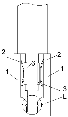
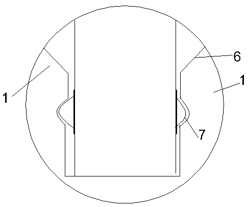
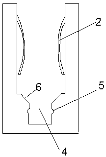
Improved imaging equipment for electrical impedance comprises a bottom plate and a through connection disc connected with the bottom plate. The through connection disc comprises a disc body, a plurality of end teeth equidistantly distributed circumferentially and radially extending from the center of the disc body are arranged at the edge of the disc body, a guide groove with a downward opening isformed at the edge of the disc body between each two adjacent end teeth, and an elastic piece conductively contacting with an electrode for the imaging equipment is mounted on one side, close to thecenter of the disc body, of each guide groove; a structure connecting the through connection disc with the bottom plate is as follows: the through connection disc is connected with the bottom plate through a clamping connection member, and the clamping connection member comprises a notch formed in the top wall of the bottom plate. The defects that a structure for threaded connection of the throughconnection disc and the bottom plate is prone to bolt loosening, threaded connection is comparatively troublesome and previous standards are quite insufficient in the aspects of information safety ofvoltage difference among to-be-detected electrodes and information transmission performance of the voltage difference among the to-be-detected electrodes when different information transmission standards coexist in the prior art are avoided effectively.

Description

technical field [0001] The invention relates to the technical field of electrical impedance imaging, in particular to an improved imaging device for electrical impedance. Background technique [0002] Electrical impedance tomography is a new medical imaging technology based on the traditional CT idea, which takes the distribution of the internal resistivity (conductivity) of the human body as the imaging target. According to the phenomenon that different tissues in the human body have different impedances, it makes full use of the rich physiological and pathological information carried by the impedance of the human body, injects current into the surface of the object to be tested through electrodes, then measures the voltage, and passes the measured voltage information through A certain algorithm is used to calculate, and finally reconstruct an image that reflects the electrical properties inside the object. [0003] In other words, Electrical Impedance Tomography (EIT) is ...

Claims


Application Information

Patent Timeline
IPC IPC(8): A61B5/053G08C17/02H04W4/80
CPCA61B5/0536G08C17/02H04W4/80
Inventor 王啸东
Owner NANJING INST OF RAILWAY TECH
Learn More