Power transmission line cleaning device

A technology for cleaning devices and power transmission lines, applied in cleaning methods and utensils, cleaning methods using tools, chemical instruments and methods, etc., to achieve the effects of improving safety factor, reducing risk factor, and preventing falling

Active Publication Date: 2019-08-16
RES INST OF ECONOMICS & TECH STATE GRID SHANDONG ELECTRIC POWER +1
View PDF8 Cites 5 Cited by
  • Summary
  • Abstract
  • Description
  • Claims
  • Application Information

AI Technical Summary

Problems solved by technology

[0007] Beneficial effects of the present invention: the clamping mechanism is arranged on the electric pole, and workers do not need to climb to the top of the electric pole, which reduces the risk factor of high-altitude operations. The gravity slides down along the pole, which improves the stability of the clamping mechanism; the control mechanism set at the left end of the clamping mechanism can control the opening and closing of the clamping part at the middle end, which is convenient for installation, and the connecting part set at the right end is for setting the lifting mechanism and cleaning The mechanism provides position support, the lifting mechanism is parallel to the insulator, and can move along the axis of the insulator, which solves the problem of manual up and down movement to complete the cleaning of the entire insulator. The lifting mechanism drives the cleaning mechanism to move up and down along the axis of the insulator

Method used


Image

  • Power transmission line cleaning device
  • Power transmission line cleaning device
  • Power transmission line cleaning device

Examples


Embodiment Construction

[0038] In order to clearly illustrate the technical features of the solution, the solution will be described below through specific implementation modes.

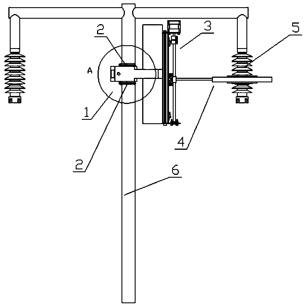
[0039] During power outage maintenance, the end that insulator 5 is connected with transmission line is disconnected, and only keeps insulator 5 and electric pole hanging point place to be connected, guarantees that insulator 5 is vertical state.

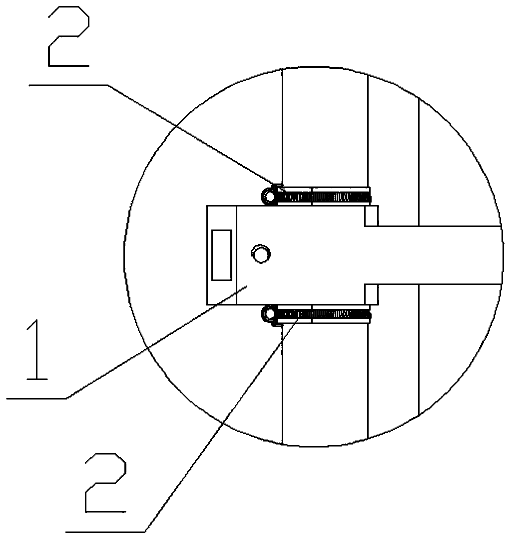
[0040] see Figure 1 to Figure 11 , the present invention is a transmission line cleaning device, including a clamping mechanism 1, the clamping mechanism 1 includes a left end, a middle end and a right end, the middle end is provided with a clamping part 11, and the clamping part 11 includes a first clamping part 111 and a The second clamping part 112, the first clamping part 111 and the second clamping part 112 are all in the shape of a semicircle, and the first clamping part 111 and the second clamping part 112 abut to form a circle whose inner diameter is equal to the diamete...


PUM


Abstract

The invention provides a power transmission line cleaning device, and belongs to the technical field of power supply equipment. According to the technical scheme, the cleaning device comprises a clamping mechanism, a hose clamp is arranged on the upper side and the lower side of the clamping mechanism respectively, the hose clamps are used for controlling the clamping mechanism to move downwards along an electric pole, the clamping mechanism comprises a left end, a middle end and a right end, a clamping part is arranged at the middle end, a control mechanism for driving the clamping part to open and close is arranged at the left end, a connecting part is arranged at the right end, a lifting mechanism is arranged on the connecting part, the direction of the lifting mechanism is parallel tothe axis direction of the electric pole, a cleaning mechanism is vertically arranged on the lifting mechanism, and the cleaning mechanism is erected between the lifting mechanism and an insulator. Thepower transmission line cleaning device has the beneficial effects that an operator do not need to go to the top of the electric pole, the body of the operator do not need to extend out for cleaningthe insulator, and the safety coefficient is improved.

Description

technical field [0001] The invention relates to the technical field of power supply equipment, in particular to a power transmission line cleaning device. Background technique [0002] An insulator is a device installed between conductors at different potentials or between a conductor and a ground potential component. It can withstand voltage and mechanical stress. An insulator is a special insulation control that can play an important role in overhead transmission lines. Insulators should not fail due to various electromechanical stresses caused by changes in the environment and electrical load conditions, otherwise the insulator will not play a significant role and will impair the service and operating life of the entire line. Insulators are affected by the environment, and the surface will be stained, which will greatly reduce the insulation performance of the insulator, and is one of the main causes of ground faults in distribution lines. Therefore, when the power line ...

Claims


Application Information

Patent Timeline
Patent Type & Authority Applications(China)
IPC IPC(8): B08B1/04B08B13/00
CPCB08B1/04B08B13/00
Inventor 朱毅韩义成夏佩源苏静华张学凯程剑董文椠丁晶王安山徐亚玮
Owner RES INST OF ECONOMICS & TECH STATE GRID SHANDONG ELECTRIC POWER
Why Eureka
Try Eureka