
Die and automatic production line using die

A technology for automated production lines and molds, applied in the field of molds and automated production lines, can solve problems such as high cost, low manual operation efficiency, and uneven quality

Inactive Publication Date: 2019-08-16
沈念涛
View PDF3 Cites 0 Cited by
  • Summary
  • Abstract
  • Description
  • Claims
  • Application Information

AI Technical Summary

Problems solved by technology

[0003] In view of the deficiencies in the prior art, the purpose of the present invention is to provide a mold and an automatic production line using the mold, which solves the problems of low manual operation efficiency, high cost, and uneven quality

Method used


Image

  • Die and automatic production line using die
  • Die and automatic production line using die
  • Die and automatic production line using die

Examples


Embodiment Construction

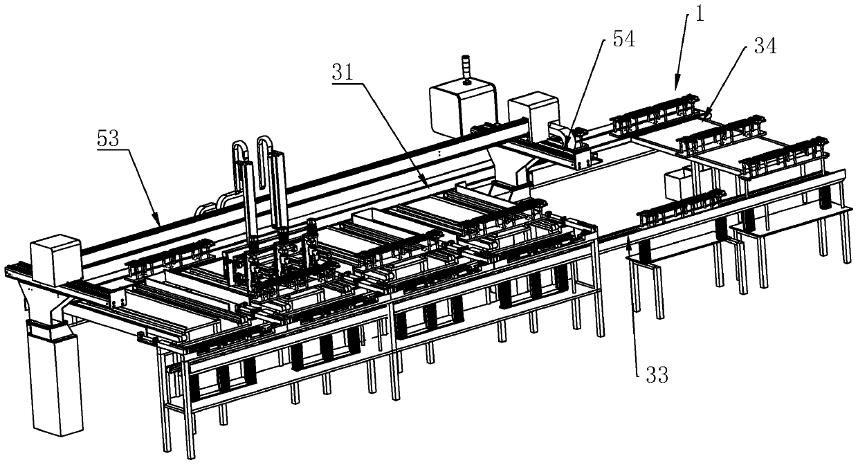
[0027] refer to Figure 1 to Figure 7 A mold of the present invention and an embodiment of an automated production line using the mold will be further described.

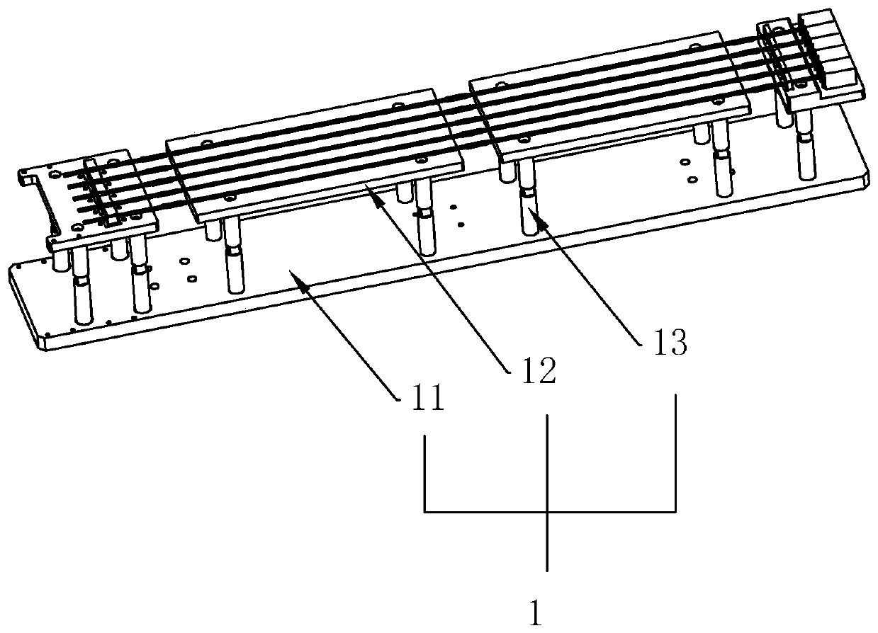
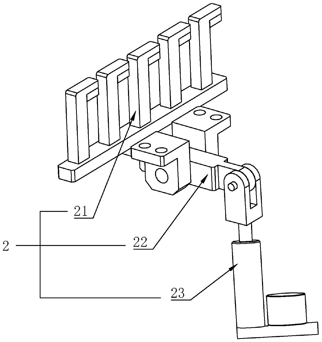
[0028] according to figure 1 As shown, a mold includes a base plate 11, a platen 12 for placing wires, and a balance column 13 for suspending the platen 12 above the base plate 11. Both the base plate 11 and the platen 12 are made of rubber and plastic materials , have high hardness and can be insulated, the deck 12 includes a first deck 12 and a second deck 12, the first deck 12 and the second deck 12 are on the same horizontal plane and arranged at intervals, the first deck 12 and the second deck Clamping mechanisms 2 for fixing wires are arranged on the boards 12 .

[0029] continue figure 1 As shown, the balance column 13 is arranged between the platen 12 and the base plate 11, so that the platen 12 is suspended in the air. The balance column 13 is mainly composed of a first connecting rod, a second connectin...


PUM


Abstract

The invention discloses a die and an automatic production line using the die. A base plate, table plates, balance columns, a moving device, a thermoplastic device, a transmission device and a first air cylinder are included. The table plates include the first table plate and the second table plate, the first table plate and the second table plate are located on the same horizontal plane and arranged in a spaced manner, and each of the first table plate and the second table plate is provided with a clamping mechanism. The moving device moves a paying-off module to the assigned position, after the transmission device is used for transmission of the thermoplastic device to the position of the paying-off module for thermoplastic forming of a heat shrinkage pipe, the moving device is matched with the first air cylinder to convey the paying-off die to the material taking position, finally, the moving device moves a discharging die obtained after material taking to the initial position, and the material taking position is located at the moving path from the first air cylinder to the initial position. By means of automatic equipment, the quality of produced products is tidy, a wire only needs to be manually placed on the die, and the labor needs are reduced, so that the labor cost is reduced.

Description

technical field [0001] The invention relates to the automatic production equipment of the heat-shrinkable tube which is sleeved on the wire, more specifically, it relates to a mold and an automatic production line using the mold. Background technique [0002] In the production of electrical appliances, it is often necessary to lengthen the wires of the components. The position where the two wires are connected will be covered with a thermoplastic tube to protect the wires and at the same time play a role in insulation. The current process is to manually align the thermoplastic tube with a hot blower to make it shrink when heated, but there are many problems. Loose, there are potential safety hazards; the second is that the efficiency of manual operation is low, and the labor cost is also relatively large. Contents of the invention [0003] In view of the deficiencies in the prior art, the object of the present invention is to provide a mold and an automatic production lin...

Claims


Application Information

Patent Timeline
IPC IPC(8): B29C63/42B29C33/12
CPCB29C33/12B29C63/42
Inventor 沈念涛左宁
Owner 沈念涛
Learn More