
Patsnap Eureka
For R&D, Patsnap Eureka makes reading and utilizing patents & technical documents easy.
Patsnap Eureka AIR
Designed for self-driven R&D workflows. Generate viable solutions, solve complex R&D challenges, empower your innovation with AI.

Patsnap Eureka Materials
Designed for material experts only. Revolutionize your material R&D, from search, analyze, to developing new materials.

TechResearch
Generate reliable direction feasibility study reports for your R&D in just a few steps.

TechSeek
Discover and master advanced knowledge NOW. Basics, ideas, possibilities, all at once.

TechMind
As an expert in R&D Theories, TechMind can generates customized viable solutions instantly.

TechRisk
Analyze your overall solution with one click, know your potential R&D risks in advance.

TechMonitor
Get weekly tech updates, stay abreast of the latest tech innovations and key insights.
Vehicular control method, vehicular system, and vehicular control device
A control method and braking device technology, applied in the direction of control devices, electric braking systems, control drives, etc.
- Summary
- Abstract
- Description
- Claims
- Application Information
AI Technical Summary
Problems solved by technology
Method used
Image

Examples
Deformed example 1
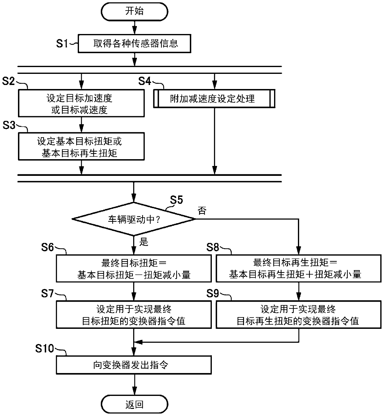
[0092] In the above-mentioned embodiment, when the vehicle attitude control is performed during the braking of the vehicle 1, the motor generator 4 is caused to perform regenerative power generation so that the vehicle 1 produces the set additional deceleration (refer to image 3 ), but in another example, when the vehicle posture is controlled during braking of the vehicle 1, a braking force may be added from the braking device 16 to cause the vehicle 1 to generate a set additional deceleration.
[0093] Figure 10 It is a flowchart of vehicle posture control processing according to a modified example of the embodiment of the present invention. Figure 10 The illustrated vehicle attitude control processing is related to the vehicle attitude control performed during braking of the vehicle 1 (the vehicle attitude control performed during driving of the vehicle 1 is related to image 3 same). In addition, the following omits the appropriate image 3 The description of the sam...
Deformed example 2
[0104] In the above-described embodiment, in the region R12 where the accelerator pedal depression amount is smaller than the predetermined value A1, the additional deceleration gain is reduced as the accelerator pedal depression amount becomes smaller (see Figure 8 ), but it is not limited to specifying the additional deceleration gain like this. In another example, in the region R12 of the accelerator pedal depression amount, when the accelerator pedal depression amount is equal to or greater than a predetermined value, the additional deceleration gain may be decreased as the accelerator pedal depression amount becomes smaller, On the other hand, when the accelerator pedal depression amount is smaller than the predetermined value, the additional deceleration gain is set to a constant value regardless of the accelerator pedal depression amount (additional deceleration gain when the accelerator pedal depression amount is greater than the predetermined value) value below the d...
Deformed example 3
[0106] In the above-mentioned embodiment, the example in which the present invention is applied to the vehicle 1 (equivalent to an EV vehicle) driven by the motor generator 4 was shown, but in another example, the present invention can also be applied to a vehicle driven by the engine. general vehicle. In this example, it is sufficient to control the vehicle attitude by reducing the generated torque of the engine and adding deceleration to the vehicle 1 . When the engine is a gasoline engine, the generated torque of the engine may be reduced by retarding (delaying) the ignition timing of the spark plug. When the engine is a diesel engine, the generated torque of the engine may be reduced by reducing the fuel injection amount. Furthermore, in another example, the present invention can also be applied to a vehicle (HV vehicle) driven by an engine and a motor generator.
PUM
 Abstract
Description
Claims
Application Information
 - R&D Engineer
- R&D Manager
- IP Professional
- Industry Leading Data Capabilities
- Powerful AI technology
- Patent DNA Extraction
Browse by: Latest US Patents, China's latest patents, Technical Efficacy Thesaurus, Application Domain, Technology Topic, Popular Technical Reports.
© 2024 PatSnap. All rights reserved.Legal|Privacy policy|Modern Slavery Act Transparency Statement|Sitemap|About US| Contact US: help@patsnap.com