Eureka AIR delivers breakthrough ideas for toughest innovation challenges, trusted by R&D personnel around the world.

Metal-sealed floating ball valve

A floating ball valve, metal sealing technology, applied in valve details, valve devices, engine components, etc., can solve the problems of poor sealing performance between the ball and the valve body cavity, the position of the ball cannot be adjusted, and the sealing performance is reduced. High sealing performance and improved functionality

Active Publication Date: 2019-08-16
XINUOWEI VALVE CONTROL SUZHOU CO LTD
View PDF5 Cites 2 Cited by
  • Summary
  • Abstract
  • Description
  • Claims
  • Application Information

AI Technical Summary

Problems solved by technology

[0004] The purpose of the present invention is to provide a metal-sealed floating ball valve to solve the problem of poor sealing performance between the ball and the inner cavity of the valve body proposed in the above-mentioned background technology, which cannot avoid the problem of long-term use causing inner wall wear, reducing sealing performance, and inconvenient control. The position of the sphere cannot be adjusted, etc.

Method used


Image

  • Metal-sealed floating ball valve
  • Metal-sealed floating ball valve
  • Metal-sealed floating ball valve

Examples


Embodiment Construction

[0023] The following will clearly and completely describe the technical solutions in the embodiments of the present invention with reference to the accompanying drawings in the embodiments of the present invention. Obviously, the described embodiments are only some, not all, embodiments of the present invention.

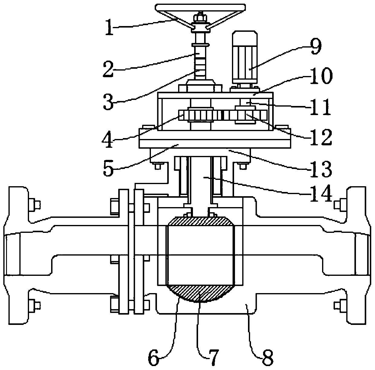
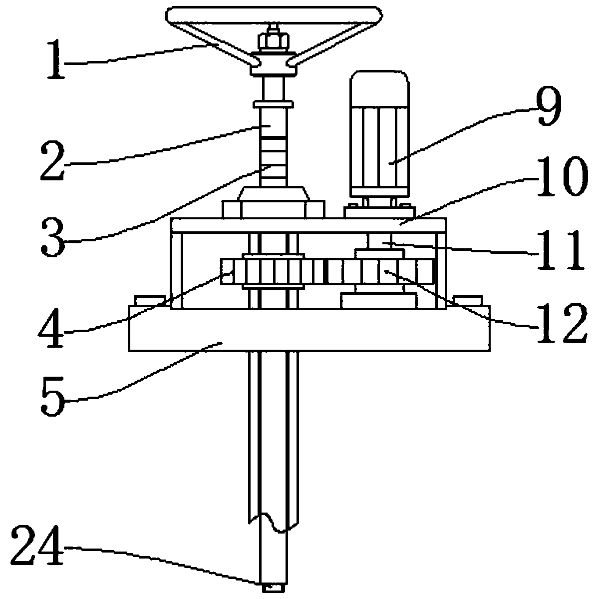
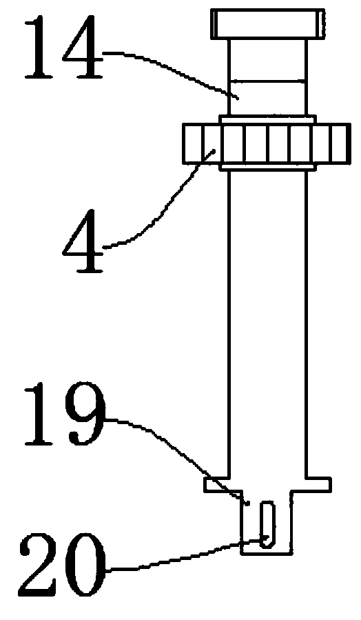
[0024] see Figure 1-5 , an embodiment provided by the present invention: a metal-sealed floating ball valve, including a valve body 8, a valve ball 7 is installed in the middle of the inner cavity of the valve body 8, and the valve ball 7 is used to seal the inner cavity of the valve body 8, Control the circulation of its inner cavity, so as to control the opening and closing of the valve body 8. There are valve ball holes 15 on both sides of the valve ball 7. The valve ball holes 15 are used to transport fluid. The top of the valve ball 7 is equipped with a top cap 21 , the top cap 21 and the bottom cap 23 are used to form the valve ball 7, so that the two ends of ...


PUM


Abstract

The invention discloses a metal-sealed floating ball valve. The metal-sealed floating ball valve comprises a valve body, a valve ball is mounted in the middle of an inner cavity of the valve body, valve ball holes are formed in the two sides of the valve ball respectively, a top cap is mounted at the top end of the valve ball, a bottom cap is mounted at the bottom end of the valve ball, a top cover is mounted at the top end of the valve body, an adjusting handle is mounted at the top end of a screw rod, an electric motor is mounted on one side of the top end of a transmission box, a driving shaft is mounted at one end of the electric motor, and a second driving gear is mounted on the driving shaft. According to the metal-sealed floating ball valve, the top cap and the bottom cap at the twoends of the valve ball are connected through a connecting strip, and the connecting strip has a certain toughness, so that the position, relative to the valve ball, of the top cap and the bottom capis capable of being floated, when a medium enters the valve ball, under the action of the medium pressure, the two ends of each of the top cap and the bottom cap can be expanded, and the two ends of each of the top cap and the bottom cap are more closely clung to the inner cavity wall of the valve body accordingly.

Description

technical field [0001] The invention relates to the technical field of floating ball valves, in particular to a metal-sealed floating ball valve. Background technique [0002] The floating ball valve controls the flow of the medium inside the valve body through the ball. The ball of the ball valve is floating. Under the action of the medium pressure, the ball can produce a certain displacement and press tightly on the sealing surface of the outlet end to ensure the seal of the outlet end. Floating The structure of the ball valve is simple and the sealing performance is good, but the load of the working medium on the ball is completely transmitted to the outlet sealing ring, so it is necessary to consider whether the material of the sealing ring can withstand the working load of the ball medium. The ball may be offset. This structure is generally used for medium and low pressure ball valves. The ball valve uses a ball with a circular through hole as the opening and closing pa...

Claims


Application Information

Patent Timeline
IPC IPC(8): F16K5/06F16K5/20F16K5/08F16K31/04F16K31/53
CPCF16K5/0605F16K5/0626F16K5/08F16K5/204F16K31/041F16K31/53
Inventor 韩泽海
Owner XINUOWEI VALVE CONTROL SUZHOU CO LTD
Why Eureka
Eureka Blog
Learn More