an optical module

A technology of optical modules and optical emitting devices, which is applied in the field of optical modules, can solve problems such as poor crosstalk effects, and achieve the effect of ensuring performance

Active Publication Date: 2021-02-12
HISENSE BROADBAND MULTIMEDIA TECH
View PDF3 Cites 0 Cited by
  • Summary
  • Abstract
  • Description
  • Claims
  • Application Information

AI Technical Summary

Problems solved by technology

[0004] The present invention provides an optical module to solve the problem of poor effect of the existing methods for solving crosstalk

Method used


Image

  • an optical module
  • an optical module
  • an optical module

Examples


Embodiment Construction

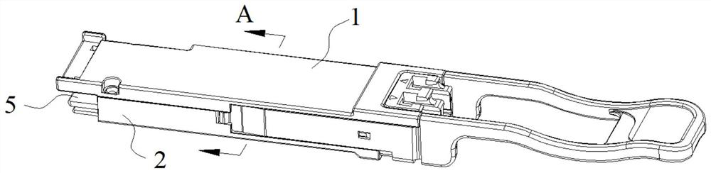
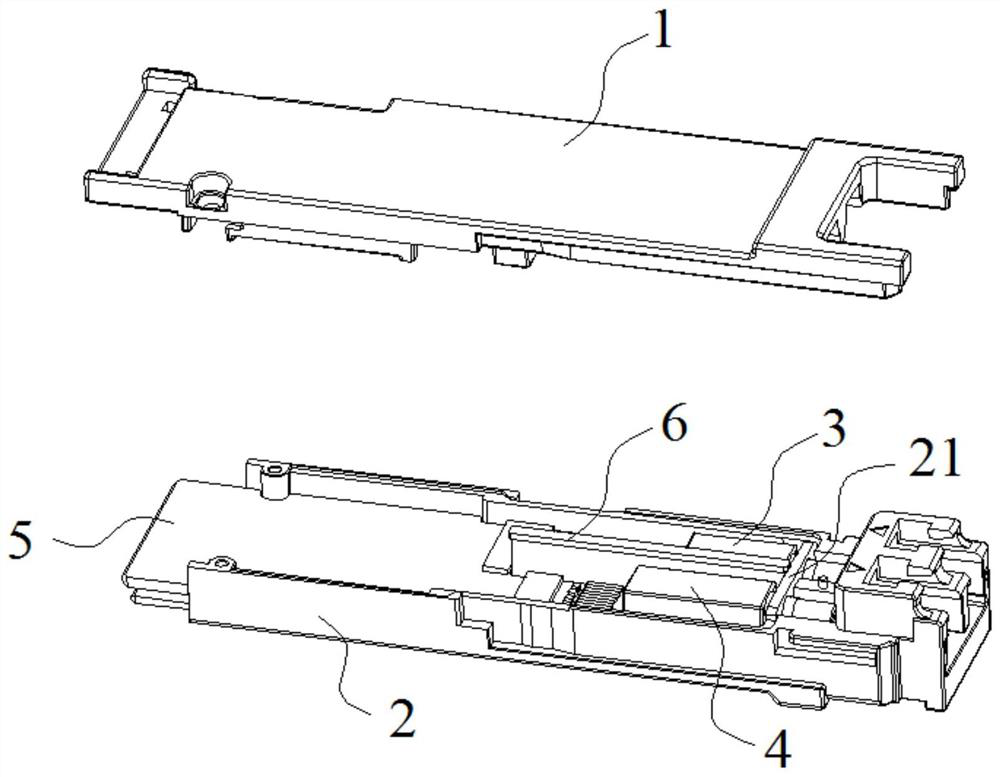
[0021] figure 1 A schematic diagram of the overall structure of the optical module provided by the embodiment of the present invention; figure 2 A schematic diagram of a partial exploded structure of an optical module provided by an embodiment of the present invention.

[0022] see figure 1 and figure 2 , an optical module provided by an embodiment of the present invention includes: a top cover 1, and a base 2 buckled with the top cover 1 to form a cavity. The top cover 1 is buckled on the base 2 to form the housing of the optical module. The housing is a hollow structure with a cavity inside, and a light receiving device 3 and a light emitting device 4 are packaged in the cavity, and a circuit board 5 is also packaged in the cavity, and both the light receiving device 3 and the light emitting device 4 are electrically connected to the circuit board 5, Both the light receiving device 3 and the light emitting device 4 are arranged on one end edge of the circuit board 5 in...


PUM


Abstract

The invention discloses an optical module, comprising: a top cover and a base, and the base is provided with an isolation rib and a fixing frame, and the fixing frame is used for shielding the front ends of the light receiving device and the light emitting device; the top cover is used for shielding the light receiving device and the light emitting device The upper end of the device; the bottom of the base is used to shield the lower end of the light receiving device and the light emitting device; When packaging the light receiving device and the light emitting device, the isolation rib is located between the light receiving device and the light emitting device, the isolation rib is used to shield the right end of the light receiving device and the left end of the light emitting device, and the two side walls of the base are used to shield the light receiving device The left end of and the right end of the light-emitting device. It can be seen that the optical module can isolate the light-receiving device and the light-emitting device, avoiding crosstalk caused by the electromagnetic waves radiated from the two optical devices and affecting each other, thereby ensuring the performance of the two devices and the normal operation of the optical module.

Description

technical field [0001] The invention relates to the technical field of optical fiber communication, in particular to an optical module. Background technique [0002] An optical module generally refers to an integrated module for photoelectric conversion, which is usually packaged by a light receiving device, a light emitting device and a circuit board. In the process of signal conversion, after the optical receiving device receives the optical signal, it will convert the optical signal into an electrical signal, and then transmit the electrical signal to the optical emitting device through the circuit board; after receiving the electrical signal, the optical emitting device will The electrical signal is converted into an optical signal and emitted, thereby realizing the conversion of the photoelectric signal. [0003] When the optical module is working, both the light receiving device and the light emitting device will radiate electromagnetic waves outward. Since the light...

Claims


Application Information

Patent Timeline
Patent Type & Authority Patents(China)
IPC IPC(8): G02B6/42
CPCG02B6/4277G02B6/4246
Inventor 陈金磊唐毅谢一帆崔峰
Owner HISENSE BROADBAND MULTIMEDIA TECH
Why Eureka
Try Eureka