
Method and device for controlling inverter

A control method and inverter technology, applied in the field of electric power, can solve problems affecting the normal operation of loads, inverter output voltage fluctuations, active or reactive power imbalance, etc.

Active Publication Date: 2019-08-16
HEFEI WIN POWER
View PDF3 Cites 9 Cited by
  • Summary
  • Abstract
  • Description
  • Claims
  • Application Information

AI Technical Summary

Problems solved by technology

[0003] However, when the inverter is switched from the off-grid mode to the grid-connected mode, because the amplitude and phase of the inverter output voltage are not synchronized with the grid, instantaneous overvoltage or overcurrent will occur when the switch operates; the grid-connected mode When switching to the off-grid mode, due to the power exchange on both sides, after the grid-connected switch is disconnected, the active or reactive power will be unbalanced, which will eventually lead to fluctuations in the output voltage of the inverter, which will affect the normal operation of the load and damage the power supply. System Reliability and Stability
[0004] The existing seamless switching control methods often only modify the calculation method of the reference current command during switching, or artificially add virtual impedance to reduce the current impact, and do not fundamentally eliminate the current impact and voltage fluctuations before switching. s reason

Method used


Image

  • Method and device for controlling inverter
  • Method and device for controlling inverter
  • Method and device for controlling inverter

Examples


Embodiment Construction

[0077] The following will clearly and completely describe the technical solutions in the embodiments of the application with reference to the drawings in the embodiments of the application. Apparently, the described embodiments are only some of the embodiments of the application, not all of them. Based on the embodiments in this application, all other embodiments obtained by persons of ordinary skill in the art without making creative efforts belong to the scope of protection of this application.

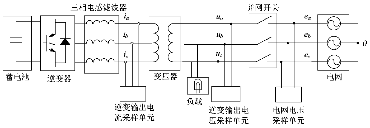
[0078] An embodiment of the present application provides a method for controlling an inverter, and the method is applied to a control component in a power system. Such as figure 1 As shown, the power system also includes a battery, an inverter, a three-phase inductive filter, a transformer, a load, a grid-connected switch, and a grid. Among them, the battery is connected to the input end of the inverter, the output end of the inverter is connected to the input end of the three-phas...


PUM


Abstract

The embodiment of the application provides a method and device for controlling an inverter, and relates to the field of power technologies. The method is applied to a control component in a power system. The power system further comprises an inverter, a power grid and a grid-connected switch, wherein the inverter is connected to the power grid through the grid-connected switch. The method comprises the steps of: when the inverter is in an off-grid state, detecting the parameter of the output voltage of the inverter and the parameter of the grid voltage of the power grid; when the parameter ofthe grid voltage satisfies a first preset grid-connected condition, instructing the output voltage of the inverter to follow the grid voltage of the grid in order that an amplitude difference, a frequency difference and a phase difference between the output voltage of the inverter and the grid voltage of the power grid satisfy a second preset grid-connected condition; when the amplitude difference, the frequency difference and the phase difference between the output voltage of the inverter and the grid voltage of the power grid satisfy the second preset grid-connected condition, turning on thegrid-connected switch. The method can reduce the current surge when the inverter is switched from a off-grid mode to a grid-connected mode.

Description

technical field [0001] The present application relates to the field of electric power technology, in particular to an inverter control method and device. Background technique [0002] The distributed energy storage microgrid system is usually composed of distributed power sources, inverters, loads, monitoring and protection devices, which can realize the flexible and efficient application of distributed power sources. The inverter in the distributed energy storage microgrid system can be disconnected from the grid and enter the off-grid mode, or it can be connected to the grid to operate in the grid-connected mode. The inverter can switch from off-grid mode to grid-connected mode, or from grid-connected mode to off-grid mode according to actual application requirements. [0003] However, when the inverter is switched from the off-grid mode to the grid-connected mode, because the amplitude and phase of the inverter output voltage are not synchronized with the grid, instantan...

Claims


Application Information

Patent Timeline
Patent Type & Authority Applications(China)
IPC IPC(8): H02J3/38H02M7/48
CPCH02J3/38H02M7/48
Inventor 张为民周一晨温圣强
Owner HEFEI WIN POWER
Learn More