Scroll compressor
A compressor and scroll-type technology, which is applied in the field of scroll compressors, can solve problems such as wear and synchronous drive mechanism life reduction, and achieve the effects of reducing noise, reducing wear, and alleviating impact
- Summary
- Abstract
- Description
- Claims
- Application Information
AI Technical Summary
Problems solved by technology
Method used
Image

Examples
no. 1 approach
[0047] Hereinafter, a first embodiment according to the present invention will be described with reference to the drawings.
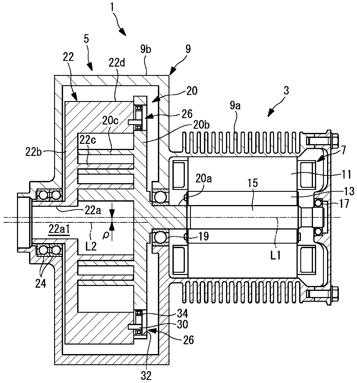
[0048] figure 1A longitudinal section of the scroll compressor 1 is shown. As shown in the figure, the scroll compressor 1 includes a drive unit 3 and a compression mechanism unit 5 in a housing 9 .
[0049] The drive unit 3 includes a motor 7 accommodated in a small-diameter portion 9 a of the housing 9 . Radiation fins are provided on the outer periphery of the small-diameter portion 9 a of the housing 9 . The electric motor 7 includes a stator 11 fixed to the housing 9 side, and a rotor 13 that rotates around a drive-side central axis L1 inside the stator 11 . The rotor 13 is fixed to the outer periphery of the rotating shaft 15 .
[0050] Both ends of the rotary shaft 15 are supported by bearings 17 and 19 . One end of the rotating shaft 15 ( figure 1 Middle left end) is connected to the shaft portion 20a of the driving scroll member 20 . T...
no. 2 approach
[0073] Next, a twin-scroll compressor according to a second embodiment of the present invention will be described. The pin ring mechanism of the present embodiment is different from the first embodiment, and the others are the same, so the pin ring mechanism will be described below.
[0074] like Figure 7 and Figure 8 As shown, the pin ring mechanism 26' includes an O-ring (intermediate member, elastic member) 38 provided on the outer periphery of the pin member 30. In addition, in this embodiment, the bushing 36 described in the first embodiment is not provided.
[0075] The O-ring 38 is provided so as to protrude outward from the outer peripheral surface of the pin member 30 in a no-load state. Thereby, even in a no-load state, the inner ring 34b is always in contact with the inner periphery of the inner ring 34b to rotate the inner ring 34b.
[0076] like Figure 8 As shown, when power is transmitted between the pin member 30 and the inner ring 34b, the O-ring 38 is ...
no. 3 approach
[0079] Next, a twin-scroll compressor according to a third embodiment of the present invention will be described. The pin fixing structure of the pin ring mechanism of this embodiment is different from each of the above-mentioned embodiments. Others are the same, so the pin-ring mechanism will be described below.
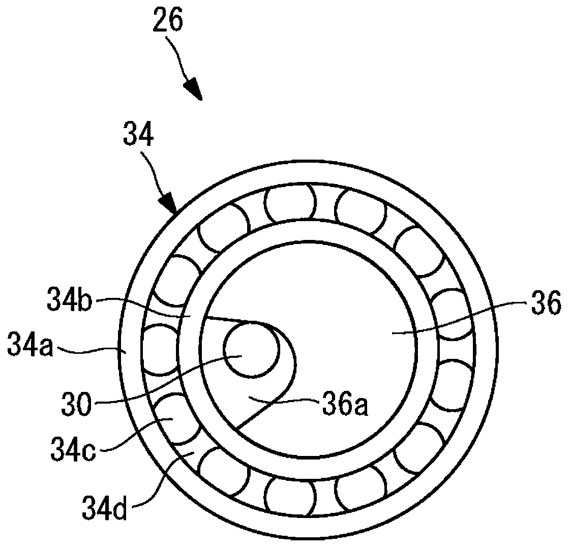
[0080] like Figure 9 As shown, the pin member 30 is made of metal, and is fixed to the outer peripheral wall portion 22d of the driven scroll member 22 opposite to the end plate 20b of the driving scroll member 20 . One end of the pin member 30 is rotatably fixed to the outer peripheral wall portion 22d of the driven scroll member 22 via a ball bearing (rolling bearing) 37 around the axis. Thus, since the pin member 30 is rotatably supported by the ball bearing 37, even if the pin member 30 comes into contact with the side wall of the bush 36 where the notch 36a is formed, it rolls without generating large friction.
[0081] In addition, in this embodiment, ther...
PUM
 Abstract
Description
Claims
Application Information
 - R&D Engineer
- R&D Manager
- IP Professional
- Industry Leading Data Capabilities
- Powerful AI technology
- Patent DNA Extraction
Browse by: Latest US Patents, China's latest patents, Technical Efficacy Thesaurus, Application Domain, Technology Topic.
© 2024 PatSnap. All rights reserved.Legal|Privacy policy|Modern Slavery Act Transparency Statement|Sitemap