Large double-color forming rotary shaft mechanism applied to automobile product mould

A technology of two-color forming and rotating shaft, applied in the field of large two-color forming rotating shaft mechanism, can solve the problems of low precision of ejector size, poor consistency of action, large workload of workers, etc. The effect of increasing the stability of the mechanism

Pending Publication Date: 2019-08-20
中山坚峰电子科技有限公司
View PDF0 Cites 0 Cited by
  • Summary
  • Abstract
  • Description
  • Claims
  • Application Information

AI Technical Summary

Problems solved by technology

[0003] The purpose of the present invention is to provide a large-scale two-color forming rotating shaft mechanism applied to automobile product molds, which has high mechanism stability, strong action continuity, high precision of ejection size, reduced workload of workers, reduced cost and better practicability. Strong advantages, can solve the problems in the prior art that the movement coherence of the manually operated machinery is not strong, the accuracy of the ejection size is low, the workload of the workers is large, and the cost increases

Method used


Image

  • Large double-color forming rotary shaft mechanism applied to automobile product mould
  • Large double-color forming rotary shaft mechanism applied to automobile product mould
  • Large double-color forming rotary shaft mechanism applied to automobile product mould

Examples


Embodiment Construction

[0022] The following will clearly and completely describe the technical solutions in the embodiments of the present invention with reference to the accompanying drawings in the embodiments of the present invention. Obviously, the described embodiments are only some, not all, embodiments of the present invention. Based on the embodiments of the present invention, all other embodiments obtained by persons of ordinary skill in the art without making creative efforts belong to the protection scope of the present invention.

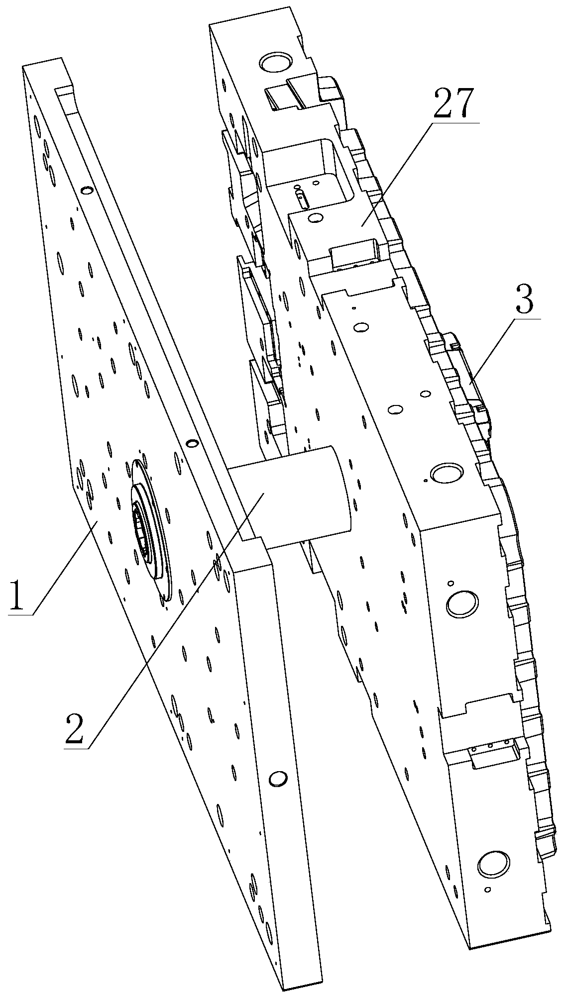
[0023] see figure 1 , a large-scale two-color forming shaft mechanism applied to automotive product molds, including a bottom plate code template 1, a forming shaft assembly 2, and a mold core 3, and the bottom plate code template 1 is movably connected through the molding shaft assembly 2 and the mold core 3.

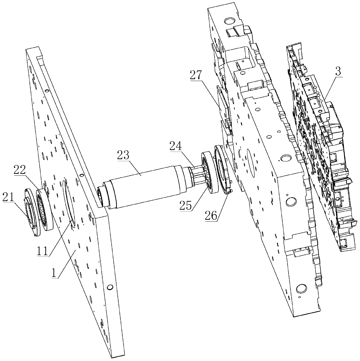
[0024] see figure 2 The first through hole 11 is processed inside the bottom plate code template 1, the forming shaft assembly 2 is installed inside...


PUM


Abstract

The invention discloses a large double-color forming rotary shaft mechanism applied to an automobile product mould. The mechanism comprises a bottom plate code template, a forming rotary shaft assembly and a mould core. The bottom plate code template is movably connected with the mould core through the forming rotary shaft assembly. The forming rotary shaft assembly is mounted between the bottom plate code template and the mould core. A rear pressing plate and a rear bearing provide support and limit for the forming rotary shaft assembly and prevent connection between the forming rotary shaftassembly and the bottom plate code template from being loosened, and the stability of the mechanism is improved; and the mould core accepts injection molding of a first-color product, the output end of a cylinder drives a cylinder ejecting rod to move rightwards so as to eject out the mould core, a PLC control chip controls the ejecting frequency of the cylinder and the rotating angle of a mounting frame according to an automated program, the mounting frame rotates to drive the mould core to rotate, the cylinder controls the mould core again to retract back to achieve mould closing, accordingly, a second-color product is injection molded, the automatic control process is matched with a mechanical structure, the action continuity is greatly improved, the ejecting size precision degree is greatly increased, mechanical equipment needs no manual control, the worker workload is reduced, and the cost is lowered.

Description

technical field [0001] The invention relates to the technical field of mold production for automobile products, in particular to a large-scale two-color forming rotating shaft mechanism applied to molds for automobile products. Background technique [0002] The proportion of plastics used in auto parts is getting higher and higher. It has been 40 years since the two-color headlights have changed from glass to plastic. Now the headlights have gradually evolved from single-color to two-color, and the molding method must also be changed. It is two-color injection molding. The process of two-color injection molding is to perform a second single-color injection on the mold core. However, after the first color injection is completed, the mold core needs to be reversed. The existing mold core reverse is manually combined with machinery. In this way, the ejection and rotation of the mold core is realized by manual operation of the machine, but the continuity of the action of the man...

Claims


Application Information

Patent Timeline
Patent Type & Authority Applications(China)
IPC IPC(8): B29C45/16B29C45/26
CPCB29C45/16B29C45/2602B29C2045/1698
Inventor 夏金锋
Owner 中山坚峰电子科技有限公司
Why Eureka
Try Eureka