Floor Thickness Control Pads

A technology for thickness control and floor slabs, which is applied in the processing of building materials, construction, building construction, etc., and can solve problems such as long construction periods

Active Publication Date: 2021-03-09
CHINA CONSTR SECOND ENG BUREAU LTD
View PDF7 Cites 0 Cited by
  • Summary
  • Abstract
  • Description
  • Claims
  • Application Information

AI Technical Summary

Problems solved by technology

[0003] The purpose of the present invention is to provide a floor thickness control pad to solve the technical problem of long construction period of the floor thickness control pad in the prior art

Method used


Image

  • Floor Thickness Control Pads
  • Floor Thickness Control Pads
  • Floor Thickness Control Pads

Examples


Embodiment Construction

[0022] In order to make the purpose, technical solution and advantages of the present invention clearer, the technical solution of the present invention will be described in detail below. Apparently, the described embodiments are only some of the embodiments of the present invention, but not all of them. Based on the embodiments of the present invention, all other implementations obtained by persons of ordinary skill in the art without making creative efforts fall within the protection scope of the present invention.

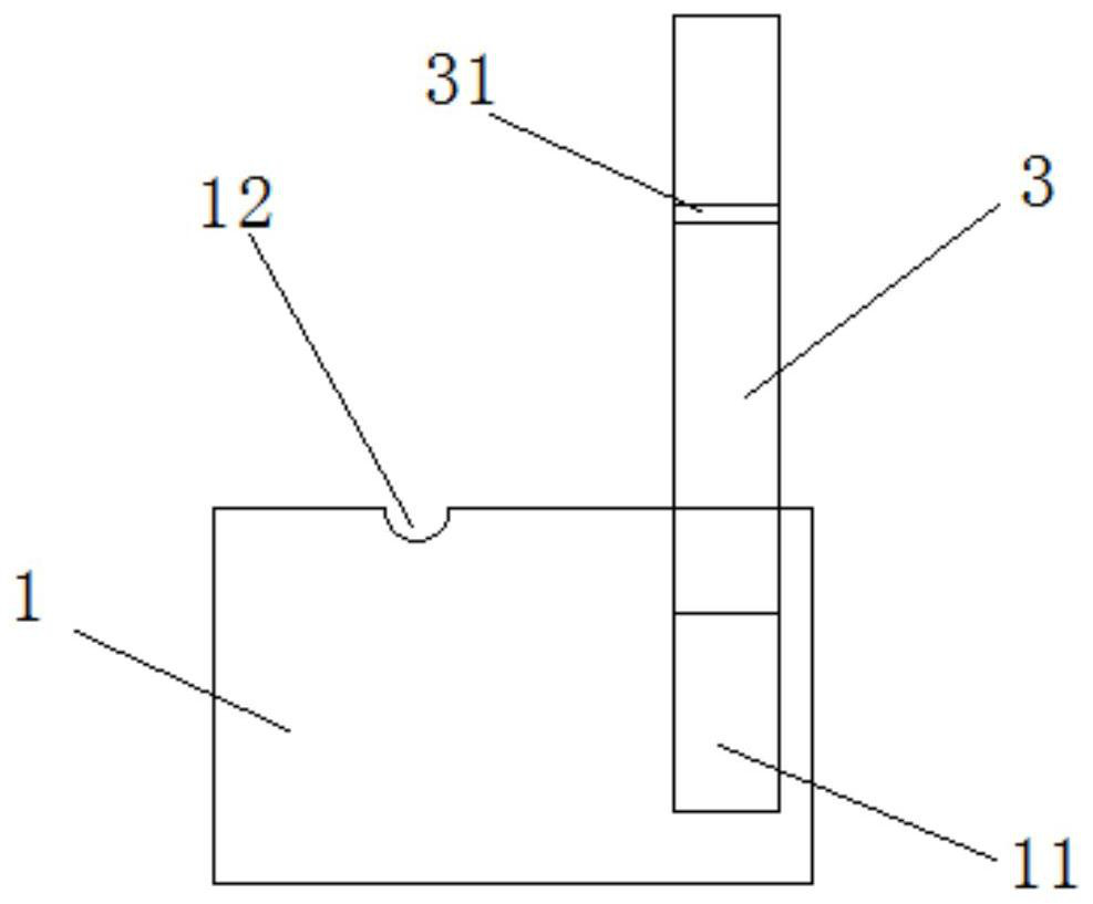
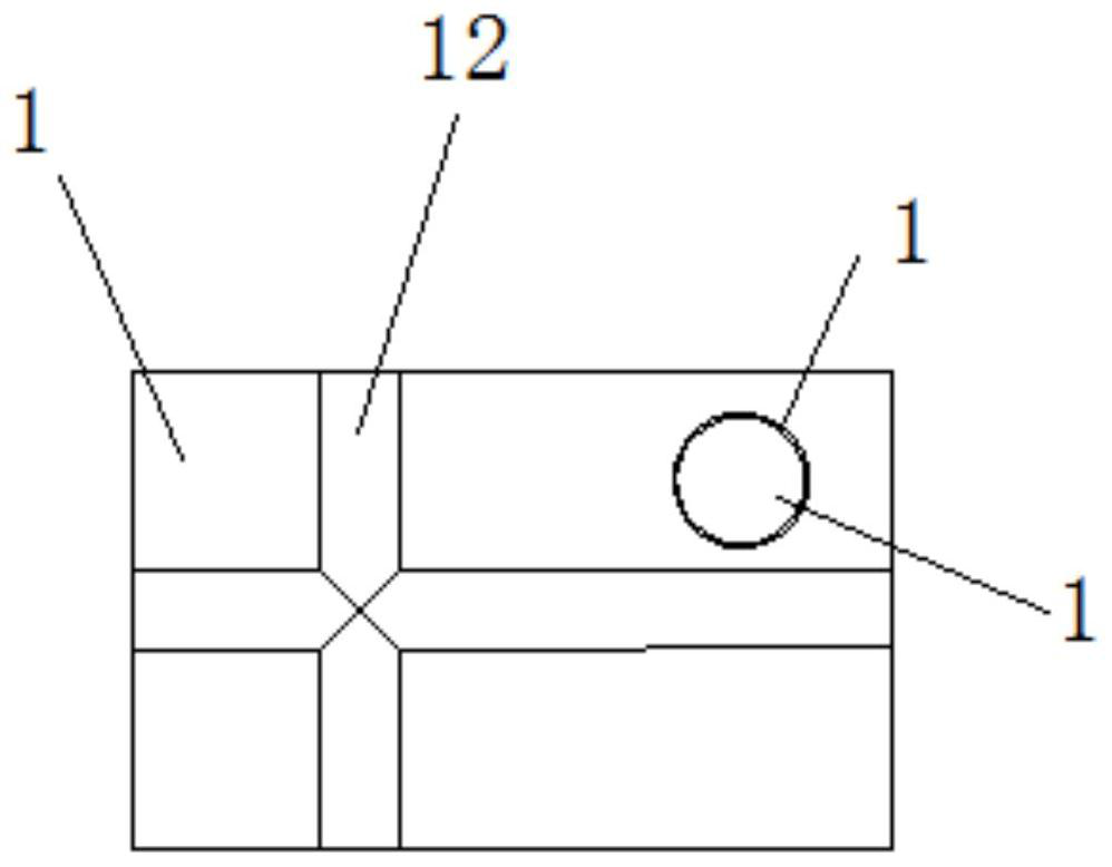
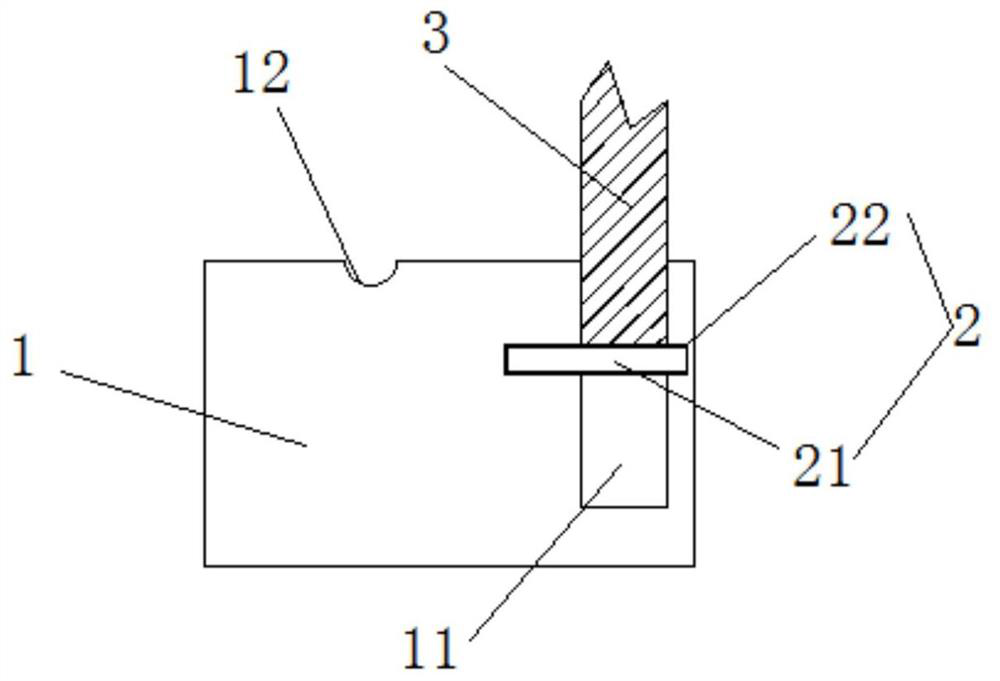
[0023] Such as figure 1 and figure 2 As shown, the present invention provides a floor thickness control pad, including a base block 1, a contraction positioning structure 2 and an indicating column 3; the base block 1 is provided with a mounting groove 11 and a first positioning groove 12; Extending in the vertical direction, the cross-section of the installation groove 11 has the same shape and size as the cross-section of the indicating column 3; the first ...


PUM


Abstract

The invention provides a floor thickness control pad, relates to the technical field of building construction, and solves the technical problem of the long construction period of the floor thickness control pad in the prior art. The floor thickness control cushion block includes a base block, a contraction positioning structure and an indicating column; the base block is provided with an installation groove and a first positioning groove; the installation groove extends in the vertical direction, and the cross section of the installation groove is the same as The shape and size of the cross-section of the indicator column are the same; the first positioning groove is horizontally arranged on the top of the base block and runs through the base block to accommodate the steel bars in the floor; the installation groove is far away from all The first positioning groove; the retractable positioning structure is arranged between the indicating column and the base block, and is used to adjust the height of the indicating column protruding from the base block. The invention is used for controlling the thickness of poured floor slabs.

Description

technical field [0001] The invention relates to the technical field of building construction, in particular to a pad for controlling the thickness of a floor slab. Background technique [0002] At present, in the construction process of the cast-in-place slab, in order to make the height and flatness of the slab meet the requirements of the design specifications, it is necessary to mark the elevation control on the reserved steel bars. After the floor slab is poured, the reserved steel bars need to be cut. The cutting process works A large amount will affect the construction progress and prolong the construction period, and will cause waste of resources. For this reason, the inventor has designed a floor height control pad that does not need to cut the reserved steel bars. Contents of the invention [0003] The purpose of the present invention is to provide a floor thickness control pad to solve the technical problem of long construction period of the floor thickness contr...

Claims


Application Information

Patent Timeline
Patent Type & Authority Patents(China)
IPC IPC(8): E04G21/10
CPCE04G21/10
Inventor 梅琦罗淳左骁冉裕成
Owner CHINA CONSTR SECOND ENG BUREAU LTD
Why Eureka
Try Eureka