
Lamp bead support plate cutting machine

A cutting machine and lamp bead technology, which is applied in metal processing and other directions, can solve the problems of insufficient precision and low cutting efficiency, and achieve the effect of improving work efficiency

Pending Publication Date: 2019-11-19
GUANGDONG HHH OPTOELECTRONICS TECH CO LTD
View PDF0 Cites 1 Cited by
  • Summary
  • Abstract
  • Description
  • Claims
  • Application Information

AI Technical Summary

Problems solved by technology

[0002] The lamp bead bracket board is produced by integrating multiple lamp bead brackets into one board with the same specification before shipment, and the manufacturer needs to cut the lamp bead bracket board when using the lamp bead bracket. It is manually fixed and cut with a cutter, which has low cutting efficiency and insufficient precision

Method used


Image

  • Lamp bead support plate cutting machine
  • Lamp bead support plate cutting machine
  • Lamp bead support plate cutting machine

Examples


Embodiment Construction

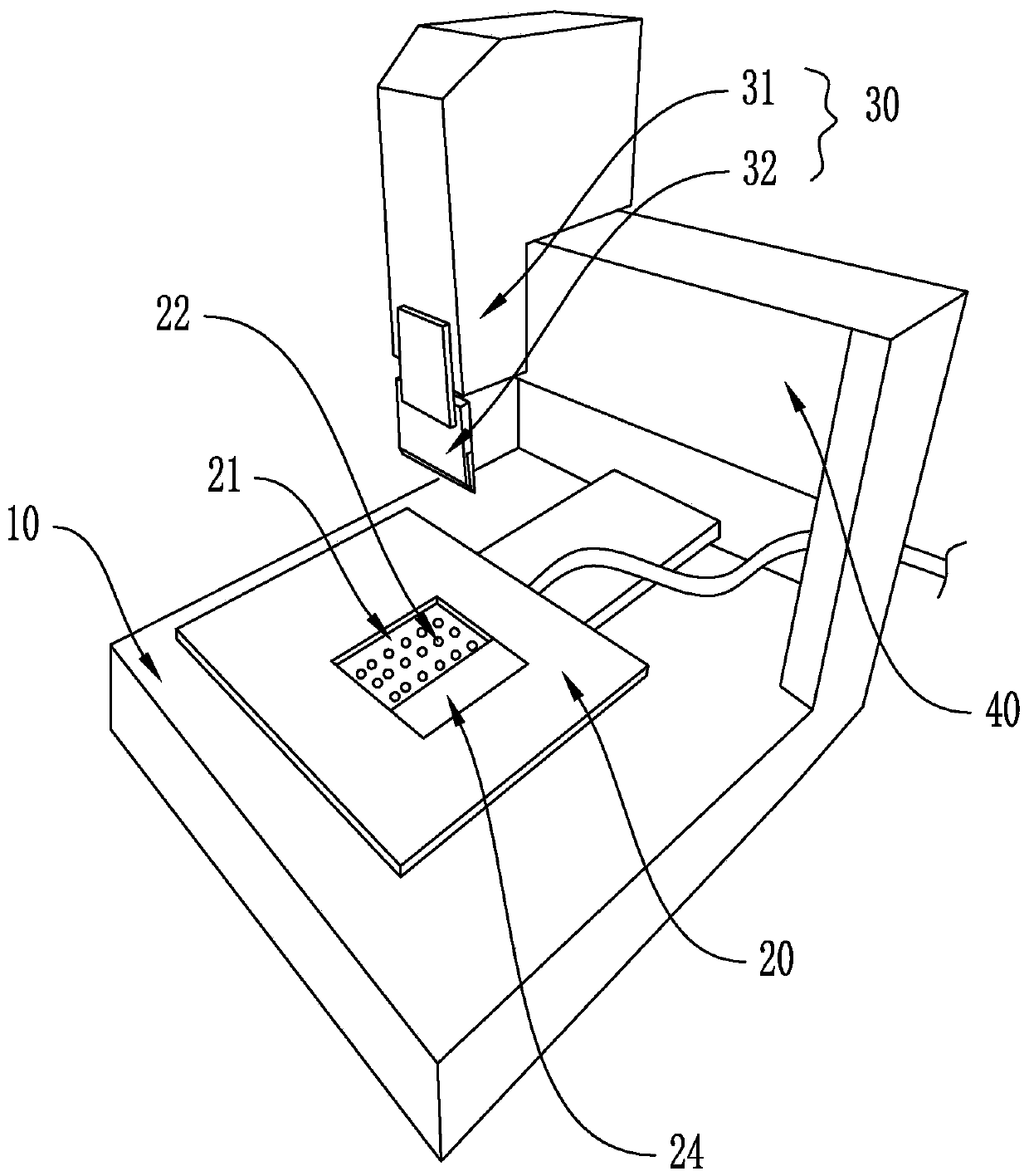
[0020] refer to figure 1 , a LED lamp bead bracket cutting machine of the present invention,

[0021] A LED lamp bead bracket cutting machine, comprising:

[0022] Machine table 10: a jig 20 that can slide on the machine table 10 is provided, and the jig 20 is provided with a groove 21 for placing the lamp bead bracket;

[0023] Cutter 30: It can be lifted up and down and cut the lamp bead bracket in the fixture 20;

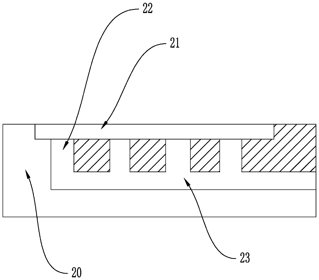
[0024] Among them, refer to image 3 , the clamp 20 is provided with several air intake passages 23, the bottom surface of the groove 21 is provided with several through holes 22, the through holes 22 correspond to the air intake passages 23 one by one, the air intake The channel 23 is connected with an air pressure device.

[0025] In actual use, the fixture 20 is used to fix the lamp bead support plate, and the up and down cutter 30 is used to cut the lamp bead support plate. During the cutting process, the fixture 20 is fed back and forth to complete the a...


PUM


Abstract

The invention discloses an LED lamp bead support cutting machine. The LED lamp bead support cutting machine comprises a machine table and a cutter, wherein the machine table is provided with a slidable clamp; the clamp is provided with a groove for placing a lamp bead support; the cutter is capable of lifting up and down and cutting the lamp bead support in the clamp; a plurality of air inlet channels are arranged in the clamp; a plurality of through holes are arranged in the bottom face of the groove; the through holes correspond to the air inlet channels one by one; and the air inlet channels are connected with an air pressure device. According to the LED lamp bead support cutting machine, the lamp bead support is fixed by the clamp and cut by the cutter which is capable of lifting up and down; and the clamp is fed back and forth in the cutting process to finish automatic cuttingofthe lamp bead support without manual fixing and cutting, so that the working efficiency is improved.

Description

technical field [0001] The invention relates to the field of lamp bead bracket processing equipment, in particular to a cutting machine for LED lamp bead brackets. Background technique [0002] The lamp bead bracket board is produced by integrating multiple lamp bead brackets into one board with the same specification before shipment, and the manufacturer needs to cut the lamp bead bracket board when using the lamp bead bracket. It is manually fixed and cut with a cutter, which has low cutting efficiency and insufficient precision. Contents of the invention [0003] The present invention aims to solve one of the above-mentioned technical problems in the related art at least to a certain extent. For this reason, the present invention proposes an LED lamp bead bracket cutting machine. [0004] The technical solution adopted by the present invention to solve its technical problems is: [0005] A LED lamp bead bracket cutting machine, comprising: [0006] Machine table: a ...

Claims


Application Information

Patent Timeline
Patent Type & Authority Applications(China)
IPC IPC(8): B26D1/08B26D7/01
CPCB26D1/08B26D7/018
Inventor 冯挺黎三科余铭彬杨华杨涛
Owner GUANGDONG HHH OPTOELECTRONICS TECH CO LTD
Learn More