Foldable inflatable tent

An inflatable tent, folding technology, applied in tents/canopies, building types, buildings, etc., can solve the problems of easy air entry at the bottom of the side walls, increase the difficulty of operation, and poor fit, and improve the overall connection performance. , Improve the effect of wind resistance and strong functionality

Pending Publication Date: 2019-08-20
YANTAI KANGQIAO OUTDOOR LEISURE PROD CO LTD
View PDF0 Cites 2 Cited by
  • Summary
  • Abstract
  • Description
  • Claims
  • Application Information

AI Technical Summary

Problems solved by technology

[0004] 1. The roof of the inflatable tent and the bracket are generally connected by rope binding or suture. In the former case of the two connection methods, because the bracket is inflated, the binding is easy to slip off, and the suture connection makes the bracket and the ceiling fixed into an integrated structure. , resulting in the need for multi-step operations from its opening to its erection, which increases the operational difficulty of its erection;
[0005] 2. The quality of the overall structure of the inflatable tent is light due to inflation, and the joint between the bottom of the side wall and the ground is not firm, which makes the side wall of the tent easy to cause a large swing when the wind blows, causing the bottom of the side wall to easily into the wind

Method used


Image

  • Foldable inflatable tent
  • Foldable inflatable tent
  • Foldable inflatable tent

Examples


Embodiment Construction

[0024] The following will clearly and completely describe the technical solutions in the embodiments of the present invention with reference to the accompanying drawings in the embodiments of the present invention. Obviously, the described embodiments are only some, not all, embodiments of the present invention. Based on the embodiments of the present invention, all other embodiments obtained by persons of ordinary skill in the art without making creative efforts belong to the protection scope of the present invention.

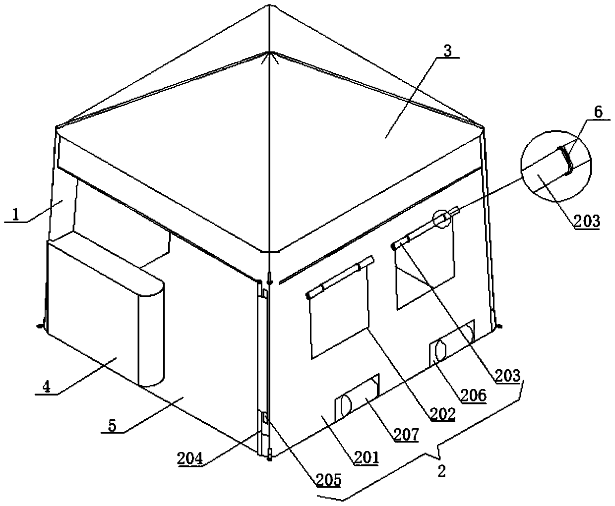
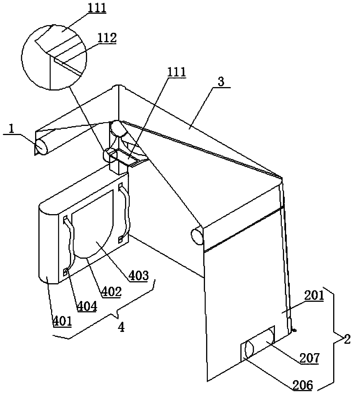
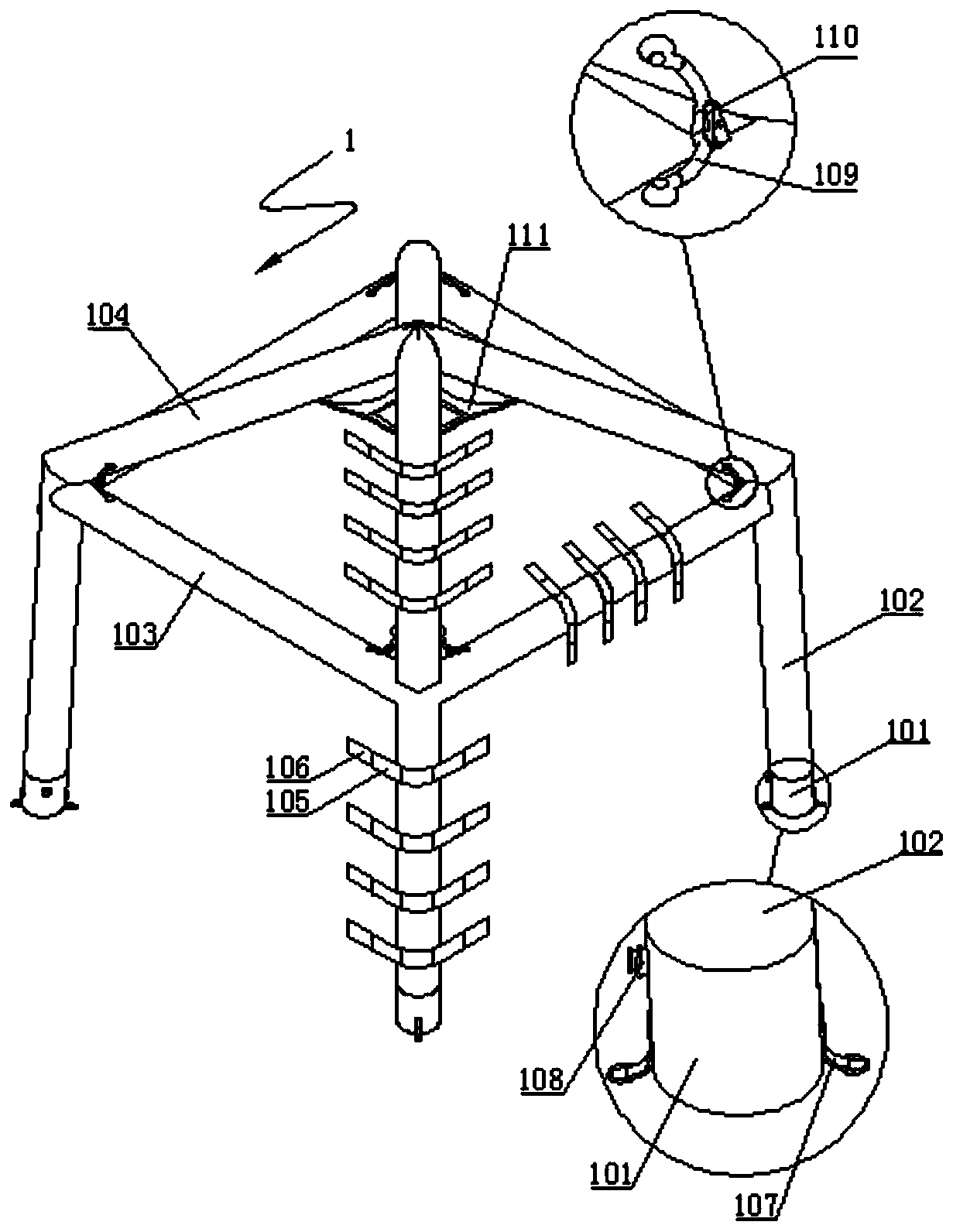
[0025] see Figure 1 to Figure 4 , the present invention provides a technical solution: a foldable inflatable tent, including an inflatable support 1, a side wall 2 on the side of the inflatable support 1, a top cover 3 and a storage bag 4 on the top of the inflatable support 1, and an inflatable support 1 The bottom of the bottom is provided with four fixed feet 101 symmetrically, and the side of the fixed feet 101 is fixedly installed with a ground nail butt...


PUM


Abstract

The invention discloses a foldable inflatable tent. The foldable inflatable tent comprises an inflation support, a side wall arranged on the side face of the inflation support, a top cover arranged onthe top of the inflation support and a storage bag. The bottom of the inflation support is provided with four fixing legs in bilateral symmetry. The side faces of the fixing legs are fixedly providedwith tent peg buckles and inflation nozzles. A vertical supporting column of a tubular structure is fixedly stitched to the upper end of each fixing leg. Horizontal supporting columns are fixedly connected to the upper ends of the vertical supporting columns and fixedly connected between every two adjacent vertical supporting columns. The inflation support, the side wall and the top cover are bonded and fixed together through the vertical supporting columns, the horizontal supporting columns, connecting bands and velcro tapes I, and the connecting bands and the velcro tapes I are arranged onthe outer side faces of ceiling supporting columns. Through the structure, the inflation support, the side wall and the top cover are effectively protected against side slipping relatively. The overall connecting performance of the whole tent is improved. The bottom edge of side wall cloth and the ground are pressed together through pressing bags, and the wind-resistant performance of the whole tent is improved.

Description

technical field [0001] The invention relates to the technical field of inflatable tents, in particular to a foldable inflatable tent. Background technique [0002] The inflatable tent is a kind of tent. It uses the principle of structural mechanics to design the frame, and uses the gas pressure characteristics to expand the airbag to form a rigid column. Inflatable tents are mainly divided into: frame type inflatable tents, integral inflatable tents and military inflatable tents. It can be quickly formed; the side wall of the integral inflatable tent and the canopy are combined into an arch, and the doors and windows are opened on demand between the two ends of the interlayer to form a special tent with overall inflatable heat preservation and sound insulation; it has high rigidity, strong stability, sound insulation, heat preservation, and molding And recovery speed and so on. [0003] Inflatable tents are not only light in weight and small in size, but also very simple t...

Claims


Application Information

Patent Timeline
Patent Type & Authority Applications(China)
IPC IPC(8): E04H15/14E04H15/20E04H15/32E04H15/62E04H15/64E04H15/56
CPCE04H15/14E04H15/20E04H15/32E04H15/56E04H15/62E04H15/64E04H2015/201
Inventor 康卫益
Owner YANTAI KANGQIAO OUTDOOR LEISURE PROD CO LTD
Why Eureka
Try Eureka