Air compressor jigger convenient to operate

An air compressor technology with convenient operation, applied in electromechanical devices, mechanical equipment, control of mechanical energy, etc., can solve the problems of wasting labor costs, time-consuming and laborious, etc., and achieve the effect of improving work stability, high safety and reliability, and simple structure

Pending Publication Date: 2019-08-20
连云港透平能源设备有限公司
View PDF0 Cites 4 Cited by
  • Summary
  • Abstract
  • Description
  • Claims
  • Application Information

AI Technical Summary

Problems solved by technology

In the past, some factories that used air compressors could only use manual rotation. Manual rotation is not only time-consuming and laborious, but also wastes a certain amount of labor costs.

Method used


Image

  • Air compressor jigger convenient to operate
  • Air compressor jigger convenient to operate

Examples


Embodiment 1

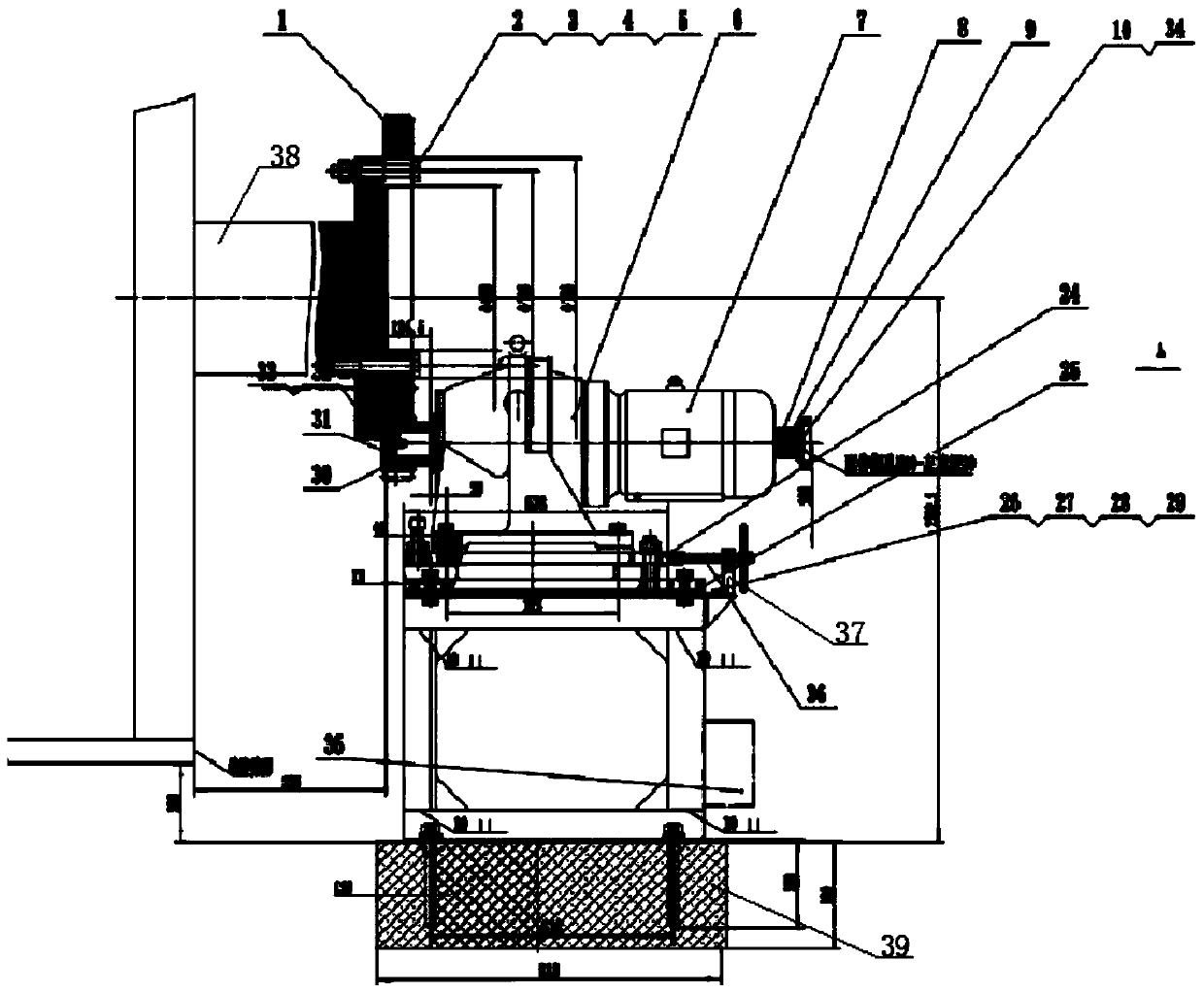
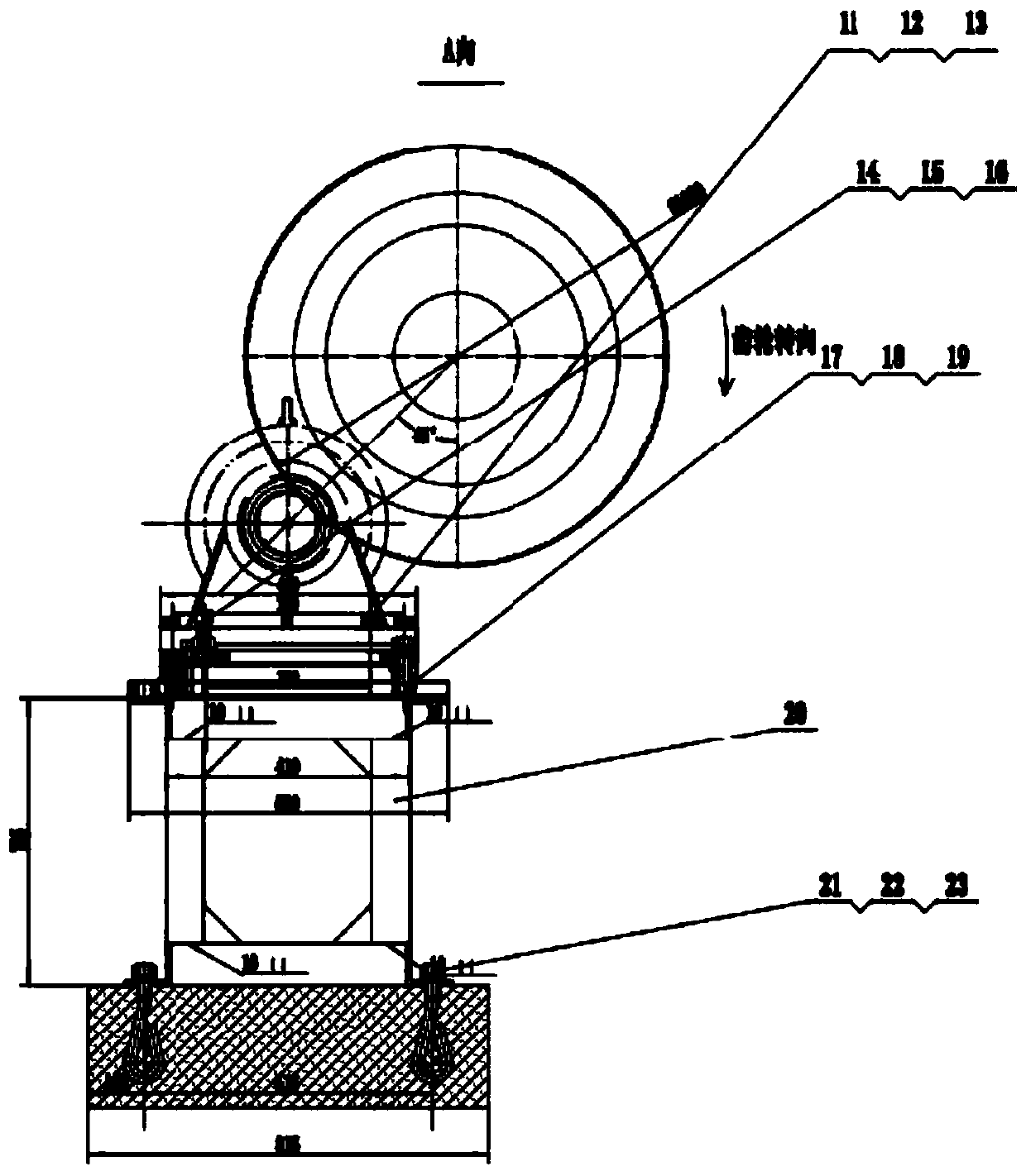
[0018] Such as Figure 1-2 As shown, a kind of easy-to-operate air compressor barring includes a small gear 30, a large ring gear 1, a reducer 6, a double shaft end motor 7, a bracket 20 and an electrical cabinet 35, and both sides of the top of the bracket 20 pass through The No. 1 bolt 26 is installed with the fixed plate II 25, the top of the No. 1 bolt 26 is threaded to the No. 1 nut 29, the top of the fixed plate II 25 is provided with a long groove, and the top of the long groove is installed with the fixed plate I 24 through a special stud 17, so The special stud bolt 17 is covered with a special washer 19 and a special spring washer 18, the top of the fixed plate I24 is installed with the reducer 6 through the second bolt 11, and the second bolt 11 is sleeved with the second spring washer 12 and the second washer 13. The double-shaft end motor 7 is installed on one side of the reducer 6 through fixing bolts, the rotating shaft on one side of the double-shaft end motor ...

Embodiment 2

[0024] Such as Figure 1-2 As shown, a kind of easy-to-operate air compressor barring includes a small gear 30, a large ring gear 1, a reducer 6, a double shaft end motor 7, a bracket 20 and an electrical cabinet 35, and both sides of the top of the bracket 20 pass through The No. 1 bolt 26 is installed with the fixed plate II 25, the top of the No. 1 bolt 26 is threaded to the No. 1 nut 29, the top of the fixed plate II 25 is provided with a long groove, and the top of the long groove is installed with the fixed plate I 24 through a special stud 17, so The speed reducer 6 is installed on the top of the fixing plate I24 through the No. 2 bolt 11, and the No. 2 spring washer 12 and the No. 2 washer 13 are sleeved on the No. 2 bolt 11. The side of the speed reducer 6 is installed with the double shaft end motor 7 through the fixing bolts. , the rotating shaft on one side of the double-shaft end motor 7 is connected to the input shaft of the reducer 6, and the rotating shaft on t...


PUM


Abstract

The invention discloses an air compressor jigger convenient to operate. The air compressor jigger convenient to operate comprises a small gear, a large gear ring, a speed reducer, a support and an electric cabinet, wherein the two sides of the top of the support are provided with a second fixing plate through first bolts, the top ends of the first bolts are connected with first nuts through threads, a long groove is formed in the top of the second fixing plate, the top of the long groove is provided with a first fixing plate through a specially-made double-head bolt, the specially-made double-head bolt is sleeved with a special gasket and a specially-made elastic pad, the top of the fixing plate is provided with a speed reducer through a second bolt, the second bolt is sleeved with a second elastic pad and a second gasket, one side of the speed reducer is provided with a double-shaft end motor through a fixing bolt, one side of the double-shaft end motor is connected with an input shaft of the speed reducer, and the other side rotating shaft of the double-shaft-end motor is provided with a hand wheel through a screw. The air compressor jigger is convenient to operate, can realize point-to-point and continuous rotation, is convenient to operate and use and meets the disc-to-turn requirement of an air compressor shaft.

Description

technical field [0001] The invention belongs to the technical field of air compressor barring, and in particular relates to an air compressor barring with convenient operation. Background technique [0002] When the air compressor is placed for a long time, the main shaft is easily deformed due to the self-weight of the shaft system. In order to avoid this situation, the main shaft must be rotated at a low speed regularly. In the past, some factories that used air compressors could only use manual rotation. Manual rotation is not only time-consuming and laborious, but also wastes a certain amount of labor costs. Contents of the invention [0003] The object of the present invention is to provide an easy-to-operate air compressor barring, which is composed of a small gear, a large ring gear, a reducer, a screw nut, a bracket, up and down adjusting bolts, left and right guiding special stud bolts, etc. The structure is simple, the cost is low, the air compressor can be jogg...

Claims


Application Information

Patent Timeline
Patent Type & Authority Applications(China)
IPC IPC(8): F04B39/00F04B35/04H02K7/116
CPCF04B35/04F04B39/00H02K7/116
Inventor 王卫国江乃东周艳
Owner 连云港透平能源设备有限公司
Why Eureka
Try Eureka