Plate bending system

A sheet metal and bending machine technology, applied in the field of sheet metal bending, can solve the problems of workers being dangerous, and the sheet is easy to hit the surrounding workers, etc., to achieve the effect of reducing labor intensity and improving production efficiency

Active Publication Date: 2019-08-23
杭州东盛五金电器有限公司
View PDF7 Cites 8 Cited by
  • Summary
  • Abstract
  • Description
  • Claims
  • Application Information

AI Technical Summary

Problems solved by technology

[0003] The above-mentioned form of manual lifting and bending of the sheet has the following disadvantages: during the short process of pressing down the punch, the side of the sheet away from the punch will rise rapidly, and the staff in order to ensure that the sheet is bent during the bending process If it does not fall, it is necessary to lift and support the board during the above process, so that the above operation process has certain dangers for the workers around the board, that is, the rapidly upturned board is easy to hit the surrounding staff

Method used


Image

  • Plate bending system
  • Plate bending system
  • Plate bending system

Examples


Embodiment 1

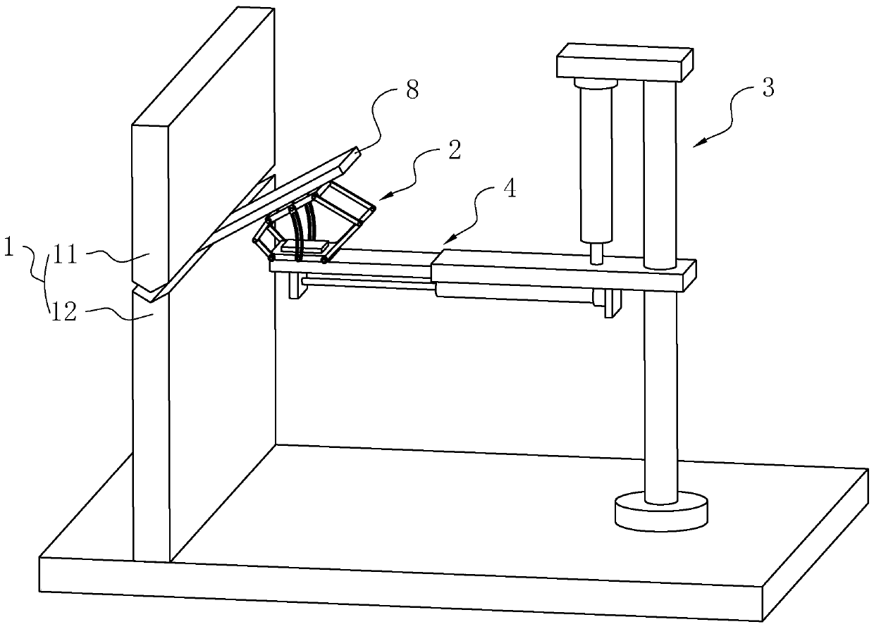
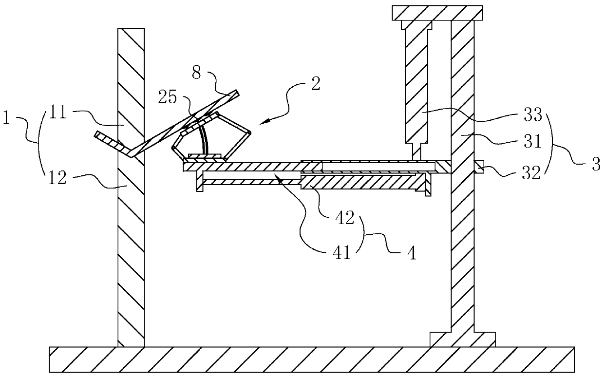
[0039] Embodiment 1: Reference figure 1 , is a plate bending system disclosed in the present invention, including a bending machine 1, the bending machine 1 includes a punch 11 and a lower die 12, and one side of the bending machine 1 is provided with a support assembly 2 for absorbing a plate 8. A first drive assembly 3 for driving the support assembly 2 to move vertically, a second drive assembly 4 for driving the support assembly 2 to approach or move away from the bending machine 1 in the horizontal direction;

[0040] The first drive assembly 3 and the second drive assembly 4 can cooperatively control the movement of the support assembly 2, and the support assembly 2 can drive the sheet material 8 to move, which can replace the manual support of the sheet material 8 to realize the bending of the sheet material 8 and reduce the bending process. , the threat of the upturned plate 8 to the surrounding operators.

[0041] refer to figure 2 and image 3 , the first drive a...

Embodiment 2

[0046] Embodiment 2: Reference Figure 4 and Figure 5 , The difference between this embodiment and Embodiment 1 is that four additional structures are added, the first place: a third drive assembly 5 is provided on one side of the bending machine 1, and the third drive assembly 5 includes: a slide rail 51 fixed on the ground 1. The third electric cylinder 52 installed on one end of the slide rail 51, the lower end of the stand 31 is slidably installed on the slide rail 51, and the third electric cylinder 52 can drive the stand 31 to slide.

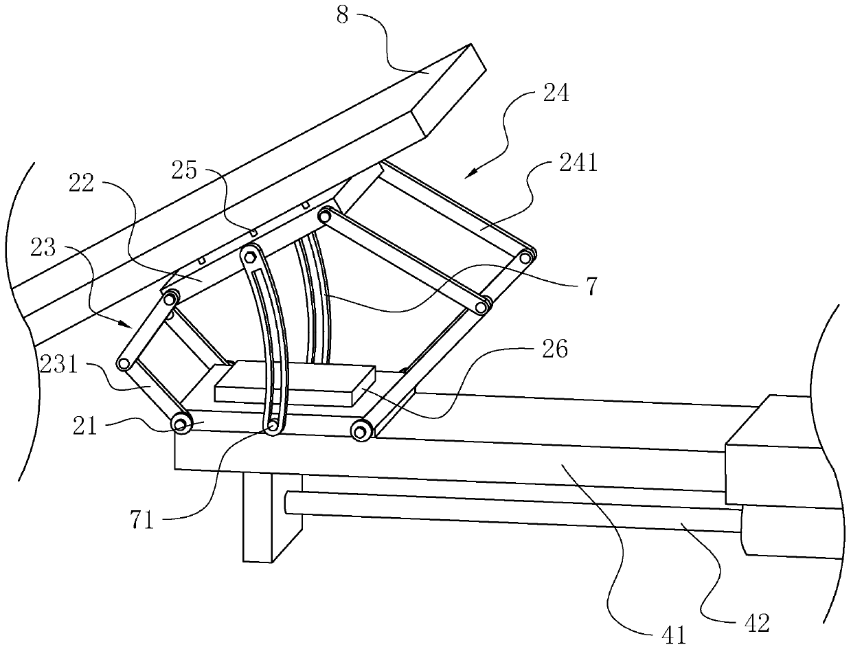
[0047] The second place: the side of the bending machine 1 close to the support assembly 2 is equipped with a plate 8 positioning frame 27, and the plate 8 positioning frame 27 is provided with a positioning port 28 on the side away from the bending machine 1; the lower side of the plate 8 positioning frame 27 is fixed and useful The supporting plate 29 is formed on the supporting plate 29, and the supporting plate 29 is located at the l...


PUM


Abstract

The invention relates to a plate bending system, and relates to the technical field of plate bending. When an existing bending machine is used for bending plates, one side of the plate can be upwardswarped, and potential safety hazards to surrounding operators are caused. The plate bending system comprises a bending machine which comprises a punching head and a lower die. One side of the bendingmachine is provided with a supporting assembly, a first driving assembly and a second driving assembly, wherein the supporting assembly is used for attracting the plates, the first driving assembly isused for driving the supporting assembly to move in the vertical direction, and the second driving assembly is used for driving the supporting assembly to be close to or far away from the bending machine in the horizontal direction. The supporting assembly comprises a fixed plate, a movable plate, a first connecting rod set, a second connecting rod set and attracting parts, wherein the first connecting rod set is connected between the fixed plate and the movable plate, the second connecting rod set is connected between the fixed plate and the movable plate, and the attracting parts are installed on the side, far away from the fixed plate, of the movable plate. According to the plate bending system, the probability of harming the operators due to upward warping of the edges of the plates can be reduced.

Description

technical field [0001] The invention relates to the technical field of plate bending, in particular to a plate bending system. Background technique [0002] Existing plate bending is usually achieved by a bending machine. For the bending of the edge of the plate, the existing more common bending form is to place the edge of the plate in a horizontal state between the punch and the lower die of the bending machine. Between, because the upper side of the lower die is provided with a V-shaped notch, and the lower end of the punch is provided with a V-shaped protrusion, the edge of the plate can be finally bent. During the bending process, usually two or more operators are required to lift the plate to the place between the punch of the bending machine and the lower die, and start the bending machine to press down the punch to realize the bending of the plate. [0003] The above-mentioned form of manual lifting and bending of the sheet has the following disadvantages: during th...

Claims


Application Information

Patent Timeline
Patent Type & Authority Applications(China)
IPC IPC(8): B21D5/02B21D43/00B21D43/14B21D45/06
CPCB21D5/002B21D5/0209B21D43/145B21D45/06
Inventor 丁盛
Owner 杭州东盛五金电器有限公司
Why Eureka
Try Eureka