
A launch vehicle sub-stage landing range control system

A launch vehicle and control system technology, applied in offensive equipment, projectiles, self-propelled projectiles, etc., can solve the problem of not having the ability to control the sub-stage landing area of ​​the launch vehicle, reduce the re-entry flight angle of attack, and improve the frontal Image, the effect of reducing secondary hazards

Active Publication Date: 2021-09-07
SHANGHAI AEROSPACE SYST ENG INST
View PDF8 Cites 0 Cited by
  • Summary
  • Abstract
  • Description
  • Claims
  • Application Information

AI Technical Summary

Problems solved by technology

my country currently does not have the ability to control the landing zone of the launch vehicle sub-stage

Method used


Image

  • A launch vehicle sub-stage landing range control system
  • A launch vehicle sub-stage landing range control system
  • A launch vehicle sub-stage landing range control system

Examples


Embodiment Construction

[0064] In order to describe the present invention in detail more clearly, the present invention will be further described below in conjunction with the accompanying drawings.

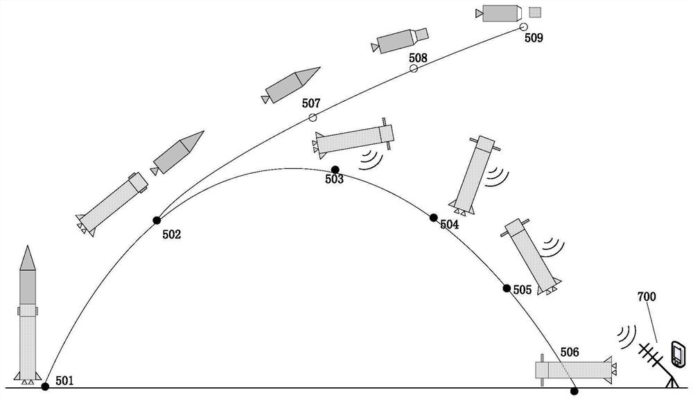
[0065] figure 1 and figure 2 The main structure and grid rudder structure system of the sub-stage body of the launch vehicle are shown. like figure 1 As shown in (a), the first-stage interstage section 101 is located at the top of the sub-stage rocket body, the box-interval section 102 is located in the middle of the sub-stage rocket body, and the engine 103 is located at the tail of the sub-stage rocket body. The control unit 300 in the grid rudder control system, the timing controller 301, the battery 302 and the telemetry unit 400 in the grid rudder telemetry system are installed in the sub-level box section 102, such as figure 1 (c) shown. A grid rudder structure system and a servo mechanism 303 are installed on the interstage section 101, figure 1 (b) The middle grid rudder surface is in the ...


PUM


Abstract

The invention discloses a control system for the range of the sub-stage landing area of ​​a carrier rocket, which comprises a grid rudder structure system, a grid rudder control system, a grid rudder telemetry system and a ground information receiving system. Under the calculation of the measurement information such as attitude, position, and speed by the control unit, the servo mechanism is sent to control the deflection of the rudder surface by sending instructions, so as to stabilize the attitude of the launch vehicle sub-stage and guide it to fly and land in the target landing area; through the telemetry system and The ground information receiving system measures and receives the sub-level re-entry flight information, and monitors the status information of the sub-level in real time. The system integrates the flight control sequence and flow disclosed in the present invention, so that it has less modification to the launch vehicle, less loss of carrying capacity, does not affect the flight safety of the main task of the launch vehicle, and can greatly reduce the range of the launch vehicle's sub-stage landing area. Real-time monitoring of child return information and other advantages.

Description

technical field [0001] The invention relates to a control system for the range of the sub-stage landing area of ​​a launch vehicle. Background technique [0002] The sub-stage landing area of ​​my country's launch vehicle is generally 30 kilometers wide and 50-70 kilometers long. At present, more than 20-30 high-density space launch missions are carried out every year, and tens of thousands of people need to be evacuated each time, and the sub-stage wreckage smashes houses High-voltage lines, farmland, highways and other civil facilities pollute water sources, causing serious harm to the lives and property of people in the landing area. Frequent and large-scale evacuations have seriously disrupted the normal life and production order of the people in the landing area and seriously affected China's aerospace industry. positive image. [0003] With the development of the drop zone economy, the population density continues to increase, and the uncertainty of the distribution of ...

Claims


Application Information

Patent Timeline
Patent Type & Authority Patents(China)
IPC IPC(8): F42B10/14F42B10/48F42B10/62F42B15/00F42B15/01
CPCF42B10/143F42B10/48F42B10/62F42B15/00F42B15/01
Inventor 陈雪巍金益辉修观夏俊力李瑞鸿郝钏钏朱亮聪古艳峰梁艳迁李鑫徐腾王吉飞
Owner SHANGHAI AEROSPACE SYST ENG INST
Learn More