Medical vehicle electrical control system

A technology of electrical control system and medical vehicle, which is applied in the direction of electrical program control and sequence/logic controller program control, etc. It can solve the problems of unsteady operation of the lifting mechanism, unadjustable speed, and many fault points, so as to prevent power failure. Insufficient power supply, speed accuracy can be controlled, and the effect of rapid monitoring and troubleshooting

Inactive Publication Date: 2019-08-23
许建明
View PDF6 Cites 1 Cited by
  • Summary
  • Abstract
  • Description
  • Claims
  • Application Information

AI Technical Summary

Problems solved by technology

[0005] Aiming at the deficiencies of the prior art, the present invention provides an electrical control system for medical vehicles, which solves the traditional relay control mode, complicated wiring, cumbersome control, many fault points and difficult troubleshooting; secondly, the current lack of intuitive screen display equipment Running status; lack of detection and protection of external sensors to limit the equipment; the lifting mechanism of traditional equipment is not stable, the speed cannot be adjusted, and the synchronization performance is poor; the lack of power display of the power supply makes it impossible to grasp the usage of the power, which will cause power failure. Insufficient accidents, during the lifting process, due to the lack of brakes, accidental falls and other problems

Method used


Image

  • Medical vehicle electrical control system
  • Medical vehicle electrical control system
  • Medical vehicle electrical control system

Examples


Embodiment Construction

[0033] The following will clearly and completely describe the technical solutions in the embodiments of the present invention with reference to the accompanying drawings in the embodiments of the present invention. Obviously, the described embodiments are only some, not all, embodiments of the present invention. Based on the embodiments of the present invention, all other embodiments obtained by persons of ordinary skill in the art without making creative efforts belong to the protection scope of the present invention.

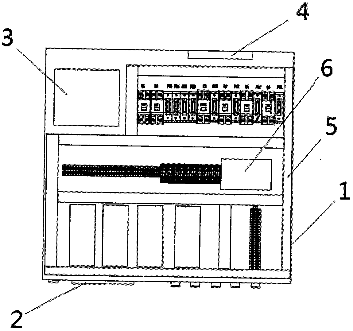
[0034] An embodiment of the present invention provides an electrical control system for a medical vehicle, such as Figure 1-6 As shown, including the electrical box housing 1;

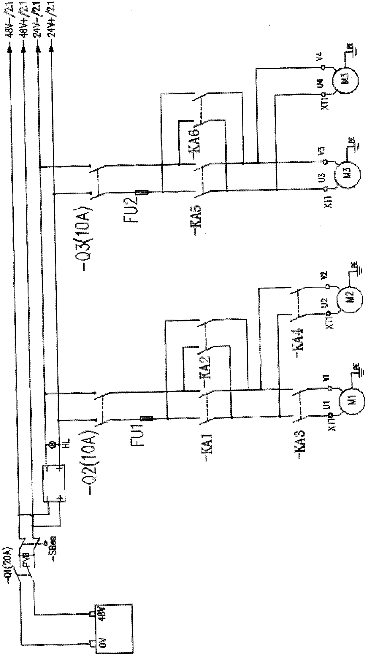
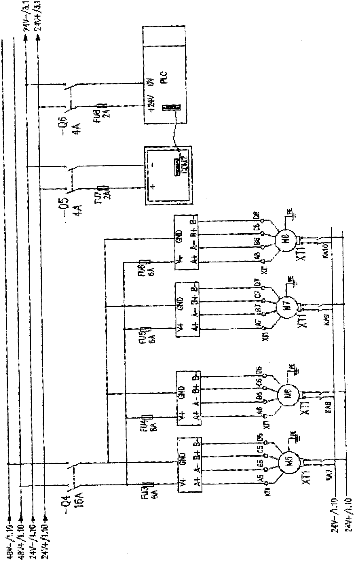
[0035] The interior of the electric box housing also includes a power supply system for driving loads and a communication control system for operating process control;

[0036] The power supply system is composed of a battery 3, a power meter, a circuit breaker and a DC converter 4; ...


PUM


Abstract

The invention discloses a medical vehicle electrical control system. The system includes an electronic box shell; and the internal of the electronic box shell also includes a power supply system usedfor driving load power and a communication control system used for operating process control. The purpose of the system is to simplify a control circuit by adopting an advanced programmable controller; through the adoption of a mode that a touch screen matches the programmable controller, the running state of equipment can be configured to the touch screen, a current state can be visually seen, and existing fault points can be foreknown in advance; when the equipment is failed and cannot be operated, reasons and timely checking can be rapidly found, an electricity meter can be increased, the electric quantity of a power supply can be displayed in real time, so that operators can be prompted to perform timely charging, accidents brought by insufficient power supply at emergency can be prevented, position limitation can be performed on an elevating mechanism by increasing an external proximity switch, overshoot can be avoided, and automatic limit can be realized; and through the adding of internal contracting brake devices on elevating motors, the internal contracting brake devices can be firmly locked lifting rods when the equipment stops, so that the falling can be prevented.

Description

technical field [0001] The invention relates to the technical field of electrical control, in particular to an electrical control system of a medical vehicle. Background technique [0002] Medical vehicles are motor vehicles used for medical examinations and medical treatment operations. They are equipped with relevant medical equipment and professional nurses and doctors. They can be divided into two categories: military and civilian according to their use objects. Military medical vehicles can be divided into X-ray vehicles, sanitary emergency vehicles, biological inspection vehicles, field surgery vehicles, medical command vehicles, military remote consultation vehicles, military shelter ambulances, etc. Detection, rescue in disaster areas, etc.; civilian medical vehicles can be divided into medical examination vehicles, blood collection vehicles, X-ray diagnostic vehicles, ambulances, surgical vehicles, etc. [0003] However, there are many inconveniences in the use of ...

Claims


Application Information

Patent Timeline
IPC IPC(8): G05B19/04
CPCG05B19/04
Inventor 周辉许建明
Owner 许建明
Why Eureka
Try Eureka