However, due to cost and technical reasons, the output
voltage waveform of traditional off-line uninterruptible power system
discharge is mostly
square wave, and the
square wave output
voltage will cause harm to some loads (such as transformers). If the
square wave output voltage When the off-line uninterruptible power system is connected to the power supply load with
power factor correction, it will also cause the over-current protection of the off-line uninterruptible power system with square wave output voltage, which will cause damage
[0003] In view of the above problems, many off-line uninterruptible power supply system devices with
sine wave voltage output have been developed. The off-line uninterruptible power supply system with
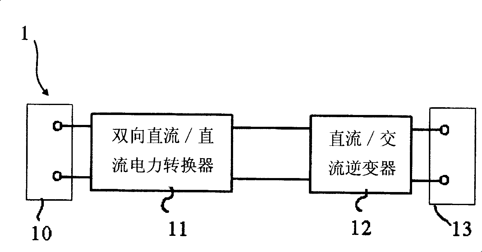
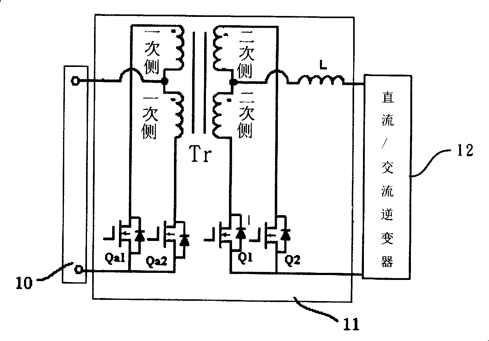
sine wave voltage output in the prior art, such as U.S. Patent No. 5,625,539, which discloses when When the mains power supply is normal, the mains supply the energy required by the load; when the mains power supply is abnormal, a unidirectional DC / DC power converter is used to boost the low-voltage DC energy stored in the battery into a higher voltage DC power, and store the power in a
DC capacitor with a large
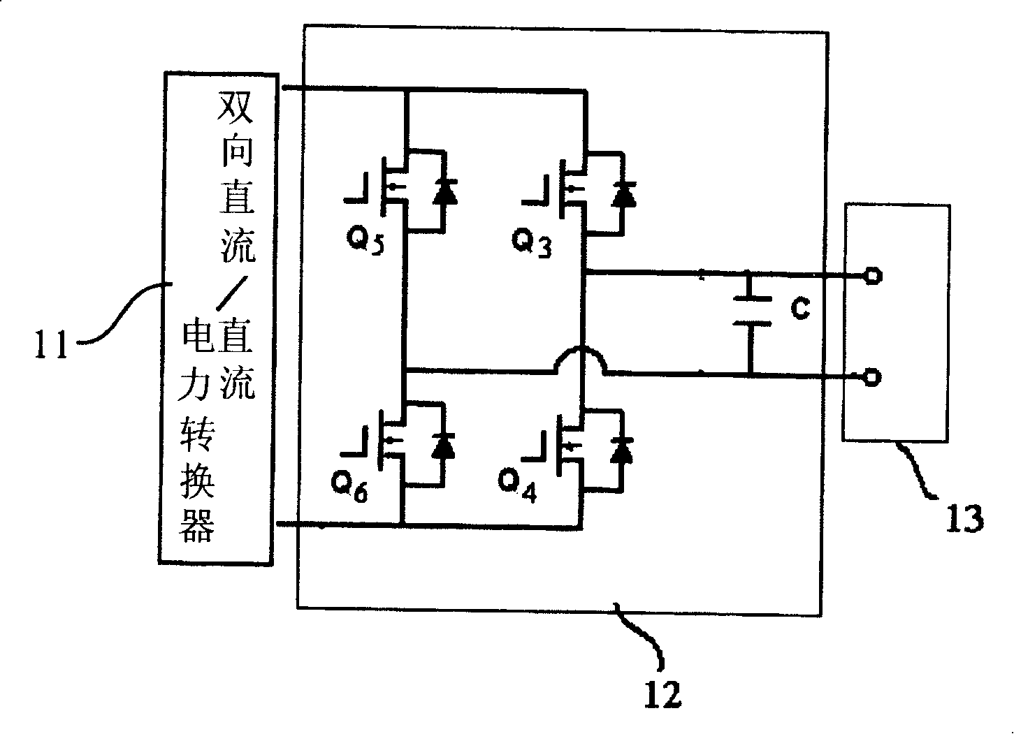
capacitance value, and then rely on a high-frequency switching full-bridge DC / AC inverter to convert the power stored in the
capacitor into a sinusoidal AC voltage and output it to the load; another set There is a group of chargers, which are responsible for charging the battery when the mains power supply is normal. The circuit structure and
control circuit are complex, and the secondary
converters are all switched at
high frequency, resulting in low efficiency; in addition, a
DC capacitor with a large
capacitance value is required As an energy buffer between secondary power
converters, it is not suitable for low-cost
sine wave output offline UPS systems
[0004] Another existing off-line uninterruptible power supply system with sine wave output, such as U.S. Patent No. 6,094,363, which discloses that when the mains power supply is normal, the energy required by the load is supplied by the mains power supply; when the mains power supply is abnormal , use a unidirectional DC / DC power converter to boost the
DC voltage of the battery into a voltage waveform similar to full-wave rectification, and then rely on low-frequency switching DC / AC inverters to convert the full-wave rectified voltage waveform into a sinusoidal AC The voltage is output to the load; there is also a set of chargers with
energy recovery function, which is responsible for charging the battery or recovering
excess energy to the battery. This circuit structure does not require a
DC capacitor with a large
capacitance value as a secondary power converter. There is only one power conversion stage for high-frequency switching, so it has the advantages of simple
control circuit and high efficiency, but it needs an additional set of chargers to charge the battery and recover the excess
load capacity, which will lead to an increase in cost
[0005] In addition, the DC terminal of the active power conditioner can also be connected to a
solar battery or other
renewable energy sources, as an energy conversion interface between the
solar battery or other
renewable energy sources and a power
distribution system, and the traditional solar cells and the power
distribution system The energy conversion interface consists of two power conversion stages (a DC /
DC converter and a DC / AC inverter), such as US Patent No. 6,914,418, which utilizes the DC /
DC converter to convert the low-voltage DC power generated by the
solar cell Convert it into high-voltage DC power and store it in a DC
capacitor with a large capacitance value, and then rely on a high-frequency switching full-bridge DC / AC inverter to convert the power stored in the DC
capacitor into a sinusoidal AC voltage output to the The load or sinusoidal
alternating current is sent back to the power
distribution system, but the two power conversion stages of the energy conversion interface of the
solar cell are controlled by high-frequency
pulse width modulation technology, and this circuit structure requires a capacitor with a large capacitance value as the secondary power The energy buffer between the
converters, the
control circuit is complicated, and the secondary converters are all switched at
high frequency, resulting in low efficiency

