Recording device and method of detecting tracking error signal and wobble signal of a wobbled track of an optical disk

a recording device and optical disk technology, applied in the field of optical disk recording, can solve the problems of affecting the quality of the recorded signal, so as to achieve the effect of increasing the number of component parts

Inactive Publication Date: 2005-08-30
YAMAHA CORP
View PDF12 Cites 26 Cited by
  • Summary
  • Abstract
  • Description
  • Claims
  • Application Information

AI Technical Summary

Benefits of technology

[0009]It is therefore an object of the present invention to provide an optical disk recording method and device which, while maintaining the advantages of the conventionally-known optical disk recording techniques, permit appropriate recording, even at high recording speeds, irrespective of residual optical axis deviations and without a need for an increased number of component parts.

Problems solved by technology

Generally, the optical axes of optical pickups employed in this type of optical recording device are factory-adjusted after manufacture of their associated disk drives; however, because the optical axes are not necessarily correctable to an ideal complete condition, the optical axis adjustment is usually judged to be acceptable as long as they fall within a permissible range (manufacturing tolerance) predetermined for the disk drives.
If recording is performed with a large tracking offset, the reproduced signals will present bad jitter measures.
Although such a verifying approach has not presented significant problems in optical disk recording at not-so-high speeds such as a four-times recording speed, it has been found that the residual optical axis deviations are not negligible either.
However, the light-transmitting flat plate can not be incorporated in the movable optical pickup and therefore has to be provided separately from the optical pickup, so that the optical path becomes considerably long.
Thus, the disclosed method would require higher adjustment accuracy, such as accurate collimation of the laser light beam and accurate optical axis angle, which involves an increased number of component parts and hence an increase in costs.
In addition, readjustment would also become necessary due to deviations over time.

Method used


Image

  • Recording device and method of detecting tracking error signal and wobble signal of a wobbled track of an optical disk
  • Recording device and method of detecting tracking error signal and wobble signal of a wobbled track of an optical disk
  • Recording device and method of detecting tracking error signal and wobble signal of a wobbled track of an optical disk

Examples


Embodiment Construction

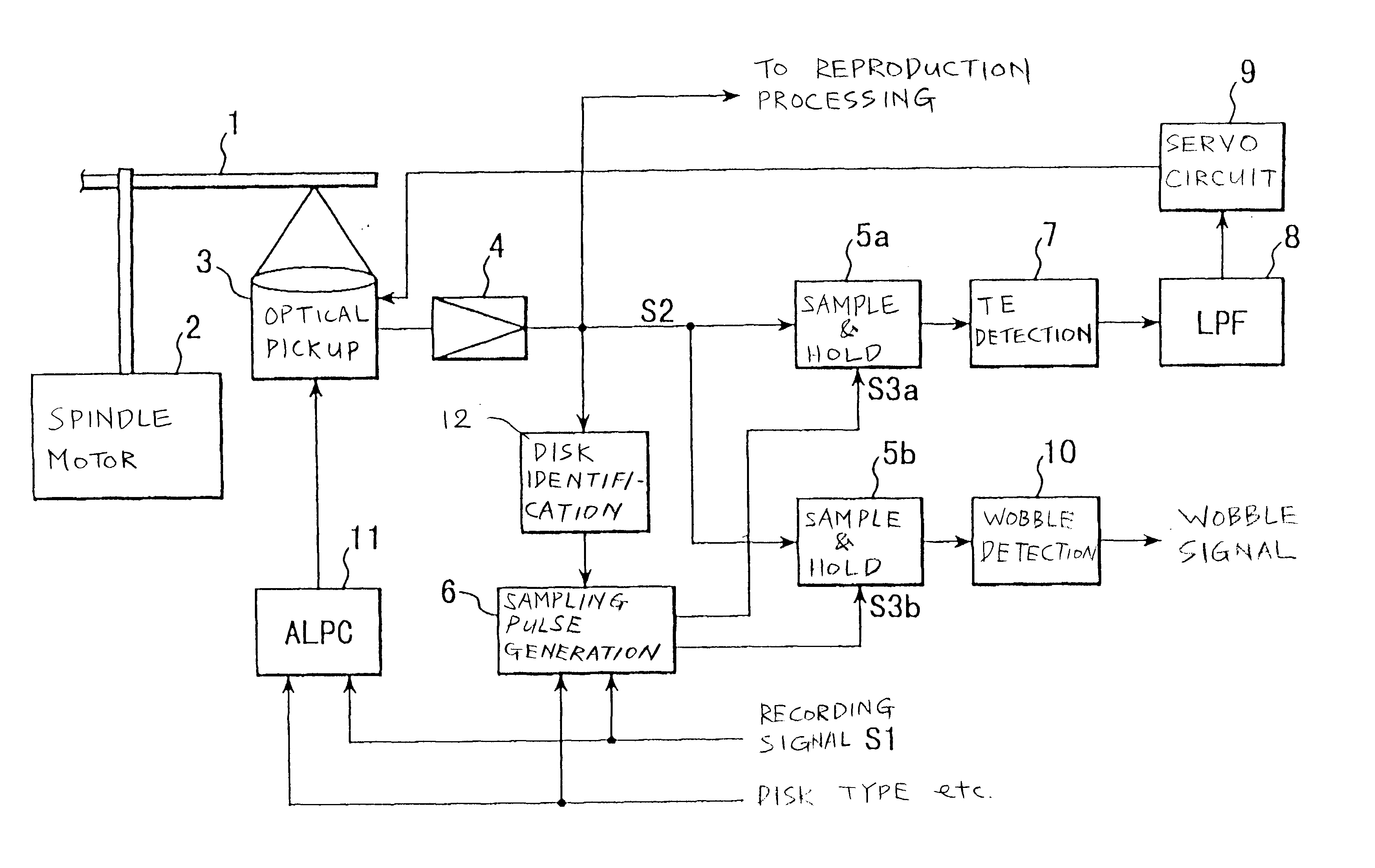
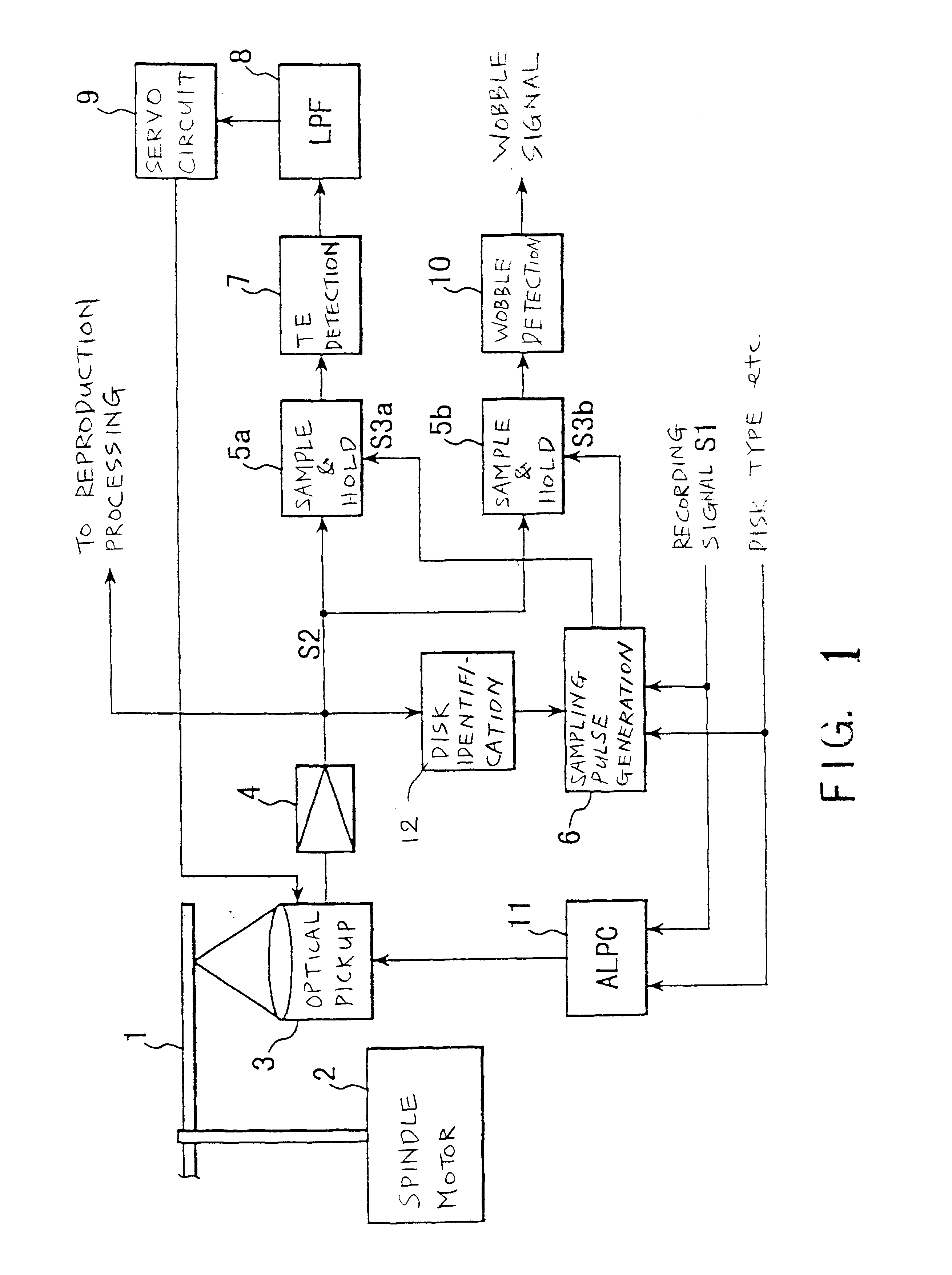
[0027]FIG. 1 is a block diagram showing an organization of principal components of an optical disk recording device in accordance with a first preferred embodiment of the present invention.

[0028]Optical disk 1 shown in FIG. 1 is of a CD-WO (Compact Disc-Write Once) type disk where a dye layer, of cyanine dye, phthalocyanine dye or diazo dye, is formed on a transparent polycarbonate substrate having lands and grooves preformed at intervals of, say, 1.6 μm. This optical disk 1 is driven via a spindle motor 2 to rotate at a constant linear velocity. Optical pickup 3 is provided in opposed relation to the recording surface of the optical disk 1. The optical pickup 3 is controllably driven to move in the radial direction of the optical disk 1 by a feed motor (not shown).

[0029]Laser diode is incorporated in the optical pickup 3, and a recording laser light beam output from the laser diode is irradiated or projected onto a land of the optical disk 1. Reflection of the thus-projected record...


PUM

PropertyMeasurementUnit
lengthsaaaaaaaaaa
timeaaaaaaaaaa
time periodaaaaaaaaaa

Abstract

In an optical disk recording device for projecting a recording light beam onto an optical disk to form 3T-11T pits in a land of the optical disk, timing to sample and hold a reflected light detection signal for tracking servo control is delayed behind timing to sample and hold the reflected light detection signal for wobble signal detection. Further, a sample-and-hold time period of the reflected light detection signal for tracking servo control is set to be shorter than a sample-and-hold time period of the reflected light detection signal for wobble signal detection. Such arrangements permit appropriate recording, even at high recording speeds, irrespective of residual optical axis deviations.

Description

BACKGROUND OF THE INVENTION[0001]The present invention relates generally to optical disk recording methods and devices for recording desired information onto optical disks, such as CD-R, CD-RW, CD-WO, MD and DVD types, using light power, and more particularly to tracking servo control and wobble signal detection during recording.[0002]Conventionally, in the pitch-forming tracks of write-once optical disks such as CD-R, CD-RW, CD-WO, MD and DVD types, there are formed grooves called “pregrooves”, which have pre-recorded therein absolute time information also known as ATIP (Absolute Time In-Pregoove). Specifically, the ATIP information is embedded in the optical disk by wobbling the track grooves, and necessary recording / reproduction control is performed on the basis of the ATIP information that is obtained by reproducing signals representative of the track wobbles (hereinafter called “wobble signals”).[0003]Tracking error and wobble signals are generally detected by processing output...

Claims


Application Information

Patent Timeline
Patent Type & Authority Patents(United States)
IPC IPC(8): G11B7/005G11B7/09G11B7/00G11B7/0045
CPCG11B7/0053G11B7/0901G11B7/0045
Inventor OGAWA, ATSUSHI
Owner YAMAHA CORP
Why Eureka
Try Eureka