Hybrid type driving apparatus

a driving apparatus and hybrid technology, applied in the direction of electric control, engine starters, snowmobiles, etc., can solve the problem of not having a hybrid technology

Inactive Publication Date: 2005-10-25
HONDA MOTOR CO LTD
View PDF14 Cites 25 Cited by
  • Summary
  • Abstract
  • Description
  • Claims
  • Application Information

AI Technical Summary

Benefits of technology

[0006]In view of the above-described circumstances, an object of the present invention is to provide a hybrid type driving apparatus that enables simplifying the driving circuit to thereby simplify the electric-power control circuit.
[0007]To attain the above object, the present invention has a first characterizing feature in that a hybrid type driving apparatus, the hybrid type driving apparatus including a generator that is driven by an engine, a battery that is electrically charged by the generator, a motor for motive-power use, and a starter motor for the engine, comprises a driving circuit that drives the motor for motive-power use with an electric power that is supplied from the generator as well as from the battery, and switching means that when starting the engine connects the driving circuit to the starter motor. According to the first characterizing feature, by making common the paths of electric power supply from the sources of electric power supply to the motor for motive-power use and to the starter motor, the driving circuit can be commonly used between the motor for motive-power use and the starter motor. Therefore, the system of electric-power control circuit can be simplified and, in addition, the system of driving circuit becomes one and the same. Therefore, the apparatus has an increased level of reliability.
[0010]Also, the present invention has a fourth characterizing feature in that the apparatus further comprises a regulator that regulates the output electric power of the generator so that the output electric power can be used for electrically charging the battery; and the switching means is constructed so that, after complete explosion of the engine, it may disconnect the generator from the driving circuit and connect the generator to the regulator. According to the fourth characterizing feature, after complete explosion of the engine, the output electric power of the generator that is driven with the engine is adjusted by the regulator to be supplied to the battery. Accordingly, the motor for motive-power use can be driven only after the engine has been subject to complete explosion. This can avoid driving the motor for motive-power use only with an electric battery power when the working place is in an environment where electrical discharging is liable to occur in the battery.
[0012]Further, the present invention has a sixth characterizing feature in that the apparatus is constructed in the way that the engine is operated so that it may be maintained at a fixed number of revolutions for a fixed speed to thereby drive a working machine; and the motor for motive-power use drives the working machine to travel. According to the sixth characterizing feature, the working machine is fixed-speed driven by the engine, while the load of the engine becomes able to be properly maintained with adjusting the travel speed of the working machine.

Problems solved by technology

However, the actual circumstance is that any contrivance has not yet been made when looked at from the viewpoint of commonly using the driving circuit.

Method used


Image

  • Hybrid type driving apparatus
  • Hybrid type driving apparatus
  • Hybrid type driving apparatus

Examples


Embodiment Construction

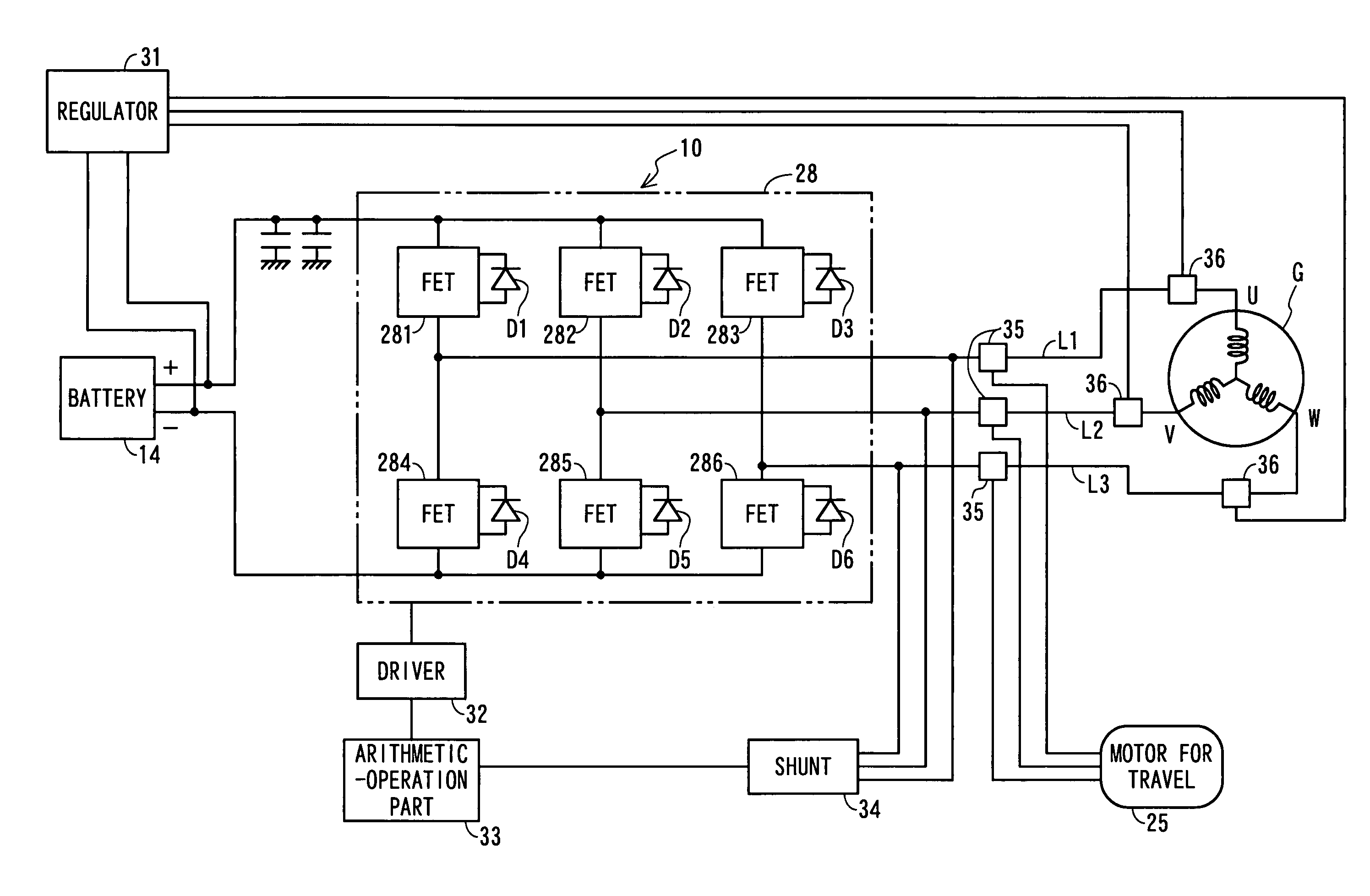
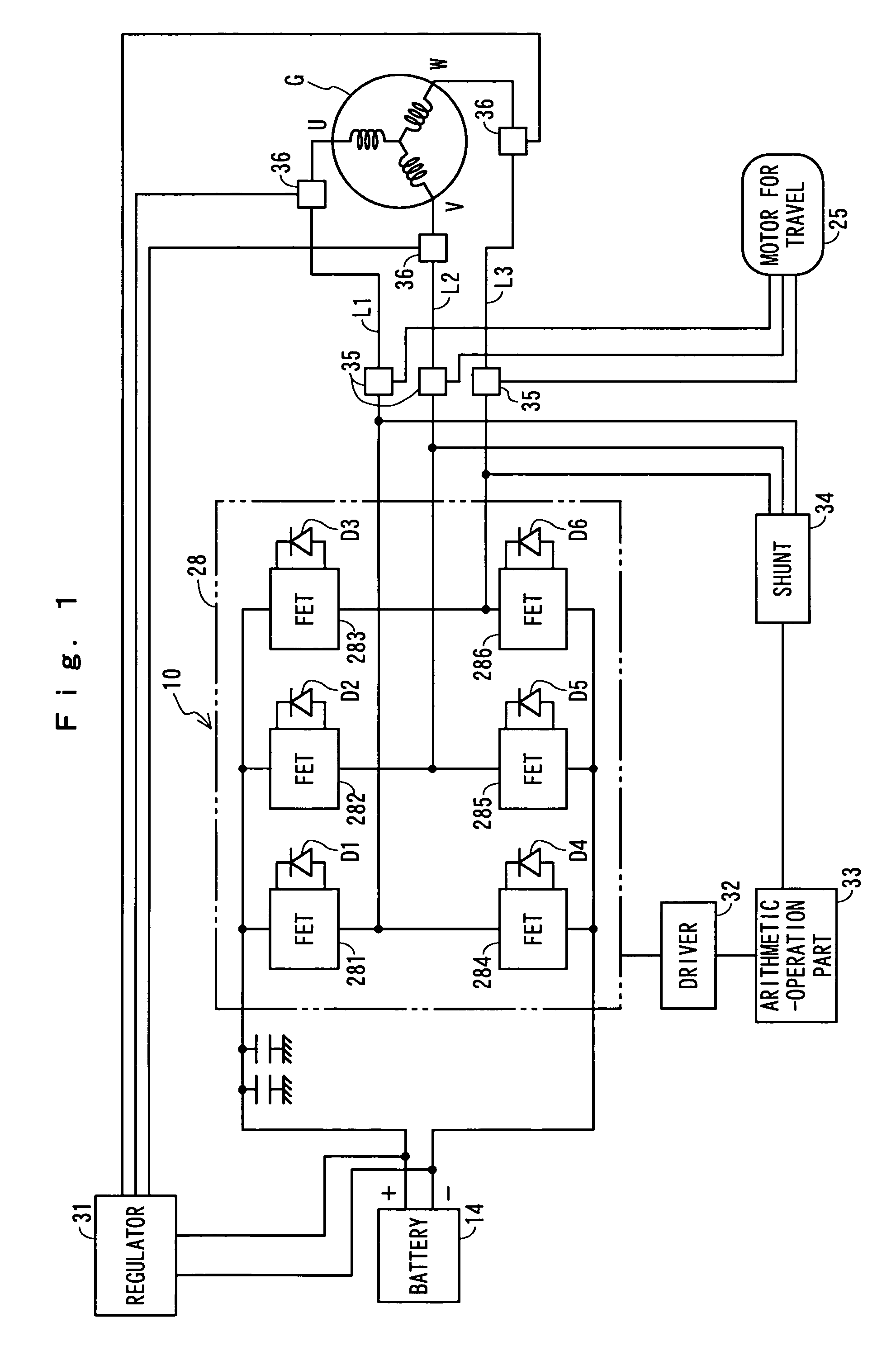
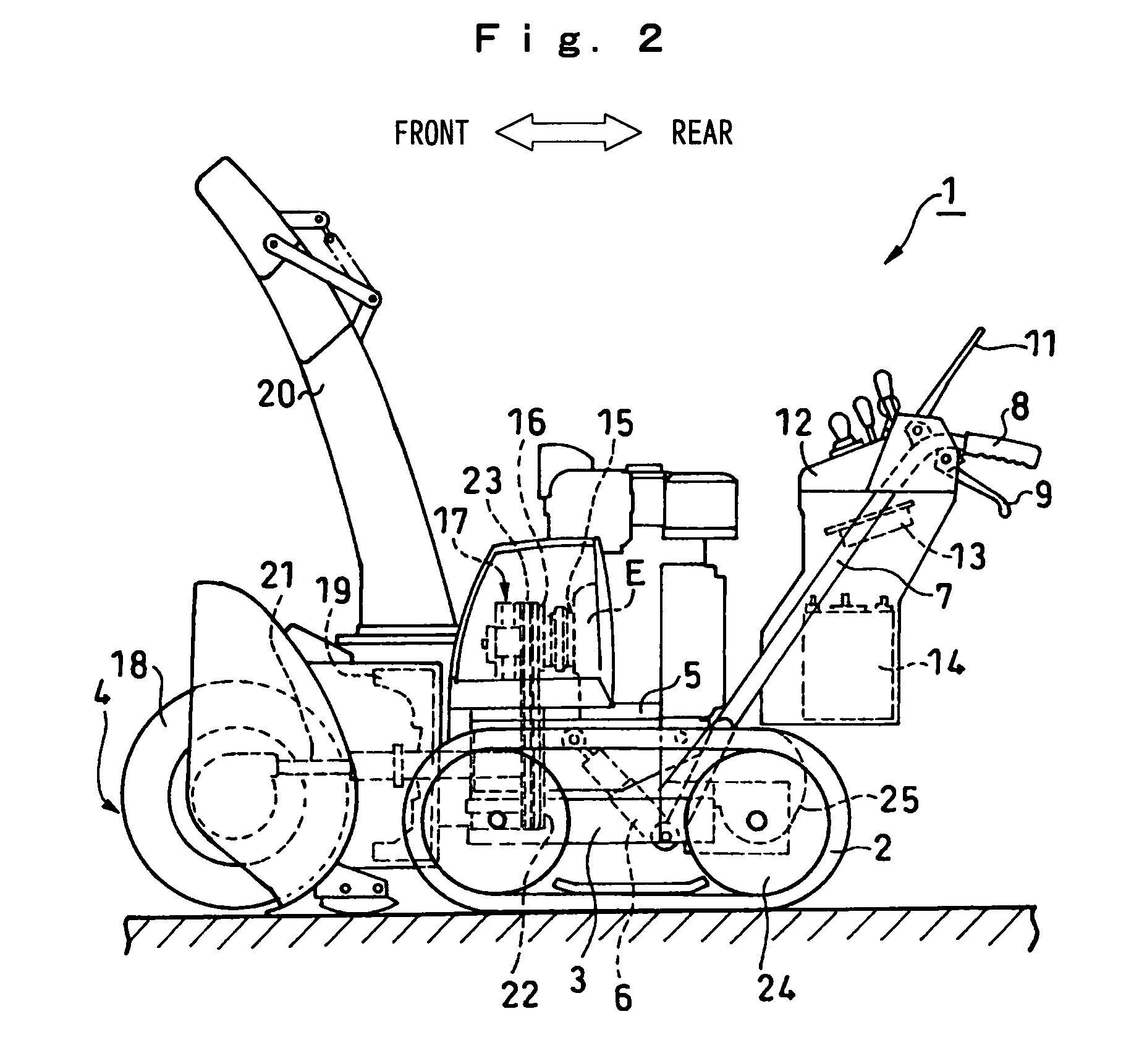
[0019]Hereinafter, an embodiment of the present invention will be explained in detail with reference to the drawings. FIG. 2 is a side view of a snowplow that serves as an engine-driven type working machine according to the embodiment of the present invention. The snowplow 1 comprises a travelling part frame 3 that is equipped with left and right crawlers 2. To this travelling part frame 3 there is attached a snow plowing body 4 as well as a vehicle body frame 5 that is equipped with an engine E that drives that snow plowing body 4, so that they can be swung up and down. The engine E drives the snow plowing body 4 that serves as the working machine by being controlled so that the engine E may be operated at a fixed number of revolutions for a fixed speed. A frame-elevating mechanism 6 swings the vehicle body 5 up and down by raising and lowering a frontward portion of the vehicle body 5. To the travelling part frame 3 there are connected left and right operation handles 7 that exten...


PUM


Abstract

An engine-driven generator G is concurrently used as a starter motor for an engine E that drives a working machine. A motor 25 for motive-power use is a driving source for the working machine to travel. The driving circuit 10 is commonly used between the starter motor G and the motor 25 for travel use. In a starting mode, with switches 35 and 36, the driving circuit 10 is connected to the starter motor G side to start the engine. After complete explosion of the engine, with the switches 35 and 36, the generator G is connected to a regulator 31, while the driving circuit 10 is connected to the motor 25 for travel use. As a result of this, while a battery 14 is electrically charged, the motor 25 for travel use is driven with the battery 14.

Description

BACKGROUND OF THE INVENTION[0001]1. Field of the Invention[0002]The present invention relates to a hybrid type driving apparatus that is equipped with an internal combustion engine and electric motor as the driving sources for a working machine, etc. and, more particularly, to a hybrid type driving apparatus that is constructed in such a way that a driving circuit can be commonly used between a motor that serves as the motive-power source for a working machine, etc. and a starter motor for the engine.[0003]2. Description of the Related Art[0004]In a working machine for agriculture use, there is known a so-called “hybrid” type engine-driven working machine that is constructed in such a way that the working machine can use the motive power of the engine and the motive power of a relevant motor. For example, in Japanese Patent Application Laid-Open No. 2001-161114, there is proposed a riding working machine that is constructed in the way that, in a case where the load of the working ma...

Claims


Application Information

Patent Timeline
Patent Type & Authority Patents(United States)
IPC IPC(8): B60L11/12B60L11/02B60K6/04B60K6/00E02F9/20B60K6/46B60L50/13B60L50/15B60L50/16B60W10/06B60W10/08B60W10/26B60W20/00F02D29/00F02D29/06F02D45/00F02N11/04F02N11/08
CPCB60K6/46B60L11/12B60W10/06B60W10/08B60W10/26B60W20/00B60Y2200/41Y02T10/6217Y02T10/6286Y02T10/7005Y02T10/7077B60K2006/268B60L50/15Y02T10/62Y02T10/70Y02T10/7072B60W2300/43B60W20/13
Inventor WAKITANI, TSUTOMUKAWAKAMI, TOSHIAKIKOBAYASHI, HIROSHI
Owner HONDA MOTOR CO LTD
Why Eureka
Try Eureka