Supercharge Your Innovation With Domain-Expert AI Agents!

Device and method for cutting a continuous strip into tire components

A cutting device and strip technology, applied in the field of tire components, can solve the problems of inaccessible space, safe access by operators, large space, etc.

Active Publication Date: 2019-08-23
VMI HOLLAND BV
View PDF13 Cites 0 Cited by
  • Summary
  • Abstract
  • Description
  • Claims
  • Application Information

AI Technical Summary

Problems solved by technology

Slack in the continuous strip consumes considerable space which cannot be safely accessed by the operator
Furthermore, when the continuous strip is fed intermittently into the cutting device, the slack is subject to unpredictable jerks and jolts

Method used


Image

  • Device and method for cutting a continuous strip into tire components
  • Device and method for cutting a continuous strip into tire components
  • Device and method for cutting a continuous strip into tire components

Examples


Embodiment Construction

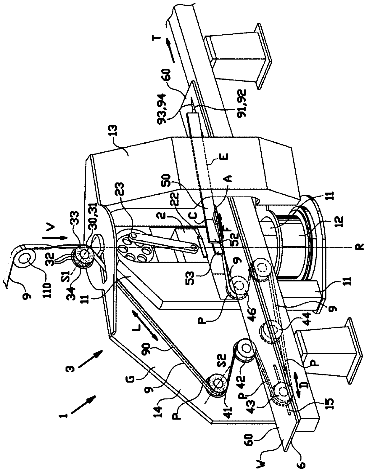
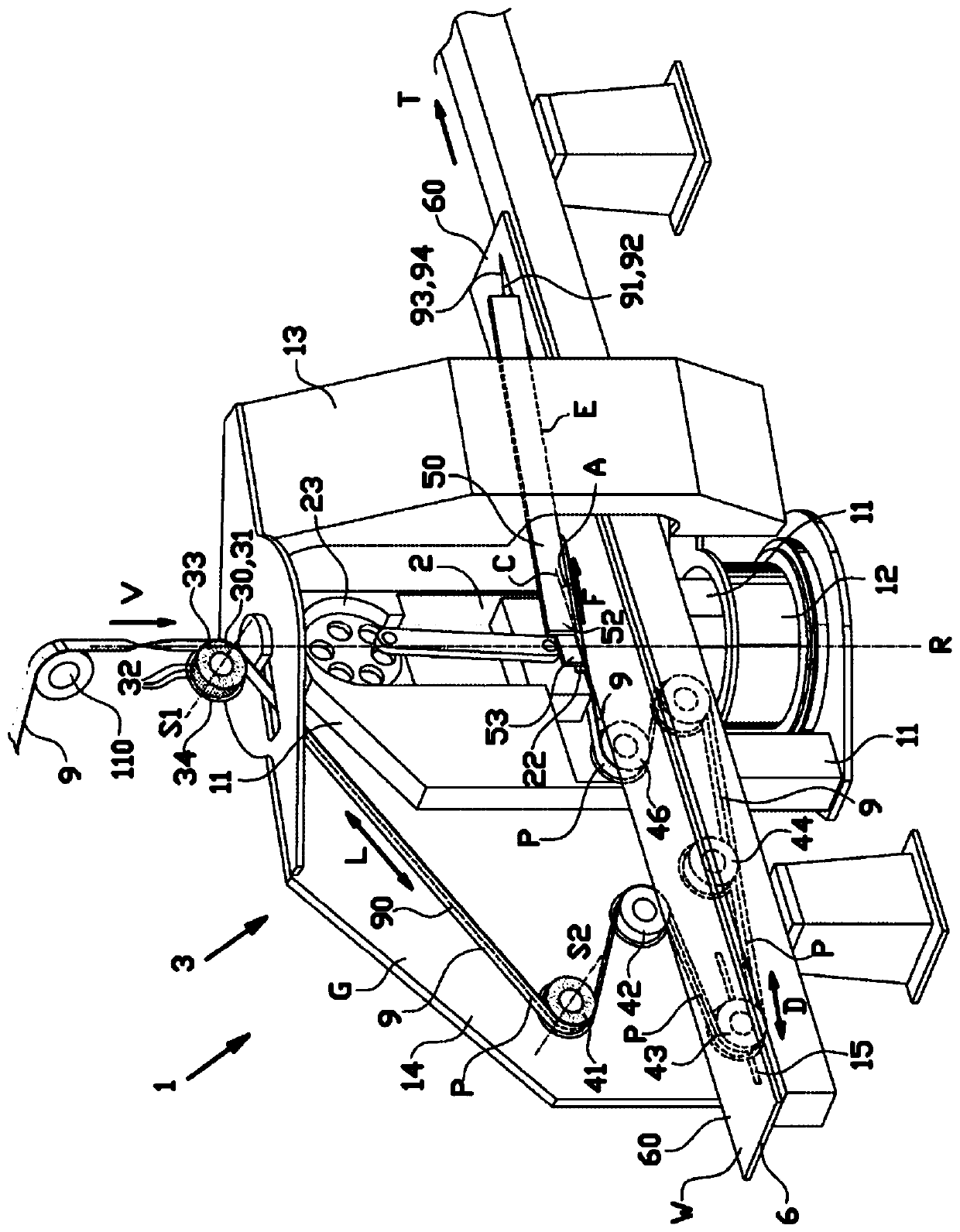
[0050] Figure 1-9 A cutting device 1 for cutting a continuous strip 9 into one or more tire components is shown according to a first embodiment of the invention. Figure 5 and Figure 6 Tire components 91 , 92 cut by the cutting device 1 at different cutting angles A are shown. Said cut tire parts 91 , 92 are preferably used in a manner known per se for building breakers 93 , 94 . The continuous strip 9 has a substantially planar main surface 90 extending in a longitudinal direction L of said continuous strip 9 and a plurality of reinforcing cords extending in the same longitudinal direction L.

[0051] Such as figure 1 , 2 As shown in and 3, the cutting device 1 comprises a knife 2 for cutting the continuous strip 9 into cut tire parts 91, 92 along a cutting line C in the working plane W, for cutting the cutting line C at a cutting angle A Feed assembly 3 that feeds the continuous strip 9 to the cutter 2 in a feed direction F of , and an output member 6 for outputting ...


PUM


Abstract

The invention relates to a cutting device (1) and a method for cutting a continuous strip (9) into tire components (91, 92), wherein the cutting device comprises a knife (2) for cutting the continuousstrip along a cutting line (C) in a working plane (W) and a feeding assembly (3) with a feeding member (50) for feeding the continuous strip in the working plane to the knife in a feeding direction (F) that intersects with the cutting line (C) at a cutting angle (A), wherein the feeding member (50) and the knife (2) are rotatable with respect to each other about a rotation axis (R) perpendicularto the working plane for adjusting the cutting angle, wherein the feeding assembly further comprises an input member (30) for receiving the continuous strip in an input direction into the cutting device and one or more guide members (40) for guiding the continuous strip from the input member to the feeding member, wherein the input member (30) is placed in line with or substantially in line with the rotation axis (R).

Description

technical field [0001] The present invention relates to a cutting device and method for cutting a continuous strip into tire components, in particular tire components for building breakers. Background technique [0002] WO 2004 / 056558 A1 discloses a known device and method for producing buffer layers. The device comprises an extrusion device for extruding unvulcanized rubber and a cooling device with a buffer circuit for cooling the extruded material. The resulting continuous rubber strip is then supplied at an angle to a cutting device by means of a conveyor. The conveyor as a whole can be rotated left and right to change the angle relative to the cutting line. as in WO2004 / 056558 A1 Figure 8 As shown in , the continuous strip is provided with considerable slack between the cooling device and the cutting device to allow rotation of the conveyor belt relative to the cooling device. The slack in the continuous strip consumes considerable space, which cannot be safely acce...

Claims


Application Information

Patent Timeline
Patent Type & Authority Applications(China)
IPC IPC(8): B29D30/46
CPCB29D30/46B26D1/085B26D7/01B26D3/003B26D3/005
Inventor A·J·斯豪滕T·J·沃布鲁基恩G·穆尔德
Owner VMI HOLLAND BV
Features
  • R&D
  • Intellectual Property
  • Life Sciences
  • Materials
  • Tech Scout
  • Unparalleled Data Quality
  • Higher Quality Content
  • 60% Fewer Hallucinations
Learn More