Connection node and method for reinforced concrete conversion column wrapping reinforced concrete conversion beam

A technology for connecting nodes and connecting methods, which is applied in the direction of construction and building construction, can solve the problems of damage to the ends of rigid concrete beams or columns, many consumables, and complex envelope structures, and achieve structural stability, cost reduction, and convenience The effect of positioning

Pending Publication Date: 2019-08-27
CITIC GUOAN CONSTR GRP CO LTD
View PDF0 Cites 0 Cited by
  • Summary
  • Abstract
  • Description
  • Claims
  • Application Information

AI Technical Summary

Problems solved by technology

[0005] The purpose of the present invention is to provide a connecting node and method for a stiffened concrete transfer column with a stiffened concrete transfer beam, so as to solve the problem of complex envelope structure at the node position and many consumables in the prior art neutral stiffened concrete combination. There is a risk of damage to the end of the stiffened concrete beam or column in the middle, to achieve the purpose of reducing the volume of the stiffened concrete joint and avoiding the risk of damage during the connection process

Method used


Image

  • Connection node and method for reinforced concrete conversion column wrapping reinforced concrete conversion beam
  • Connection node and method for reinforced concrete conversion column wrapping reinforced concrete conversion beam
  • Connection node and method for reinforced concrete conversion column wrapping reinforced concrete conversion beam

Examples


Embodiment 1

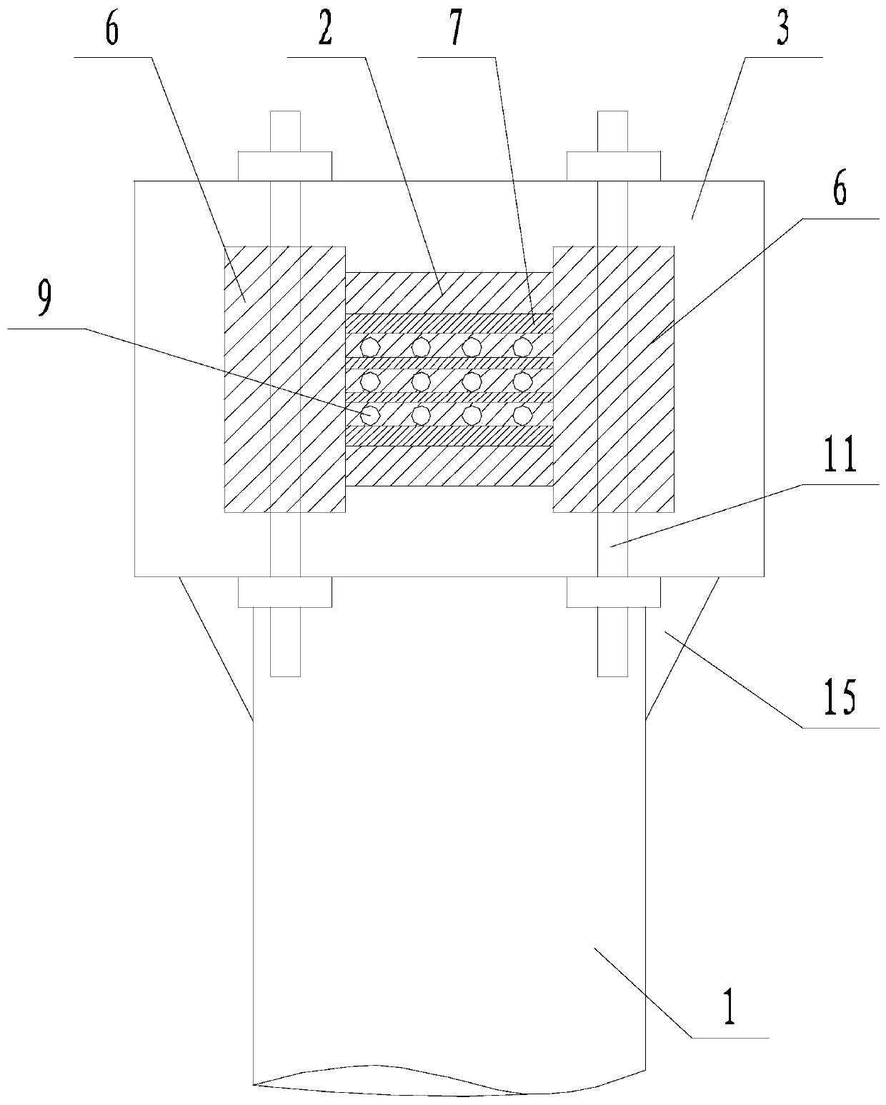
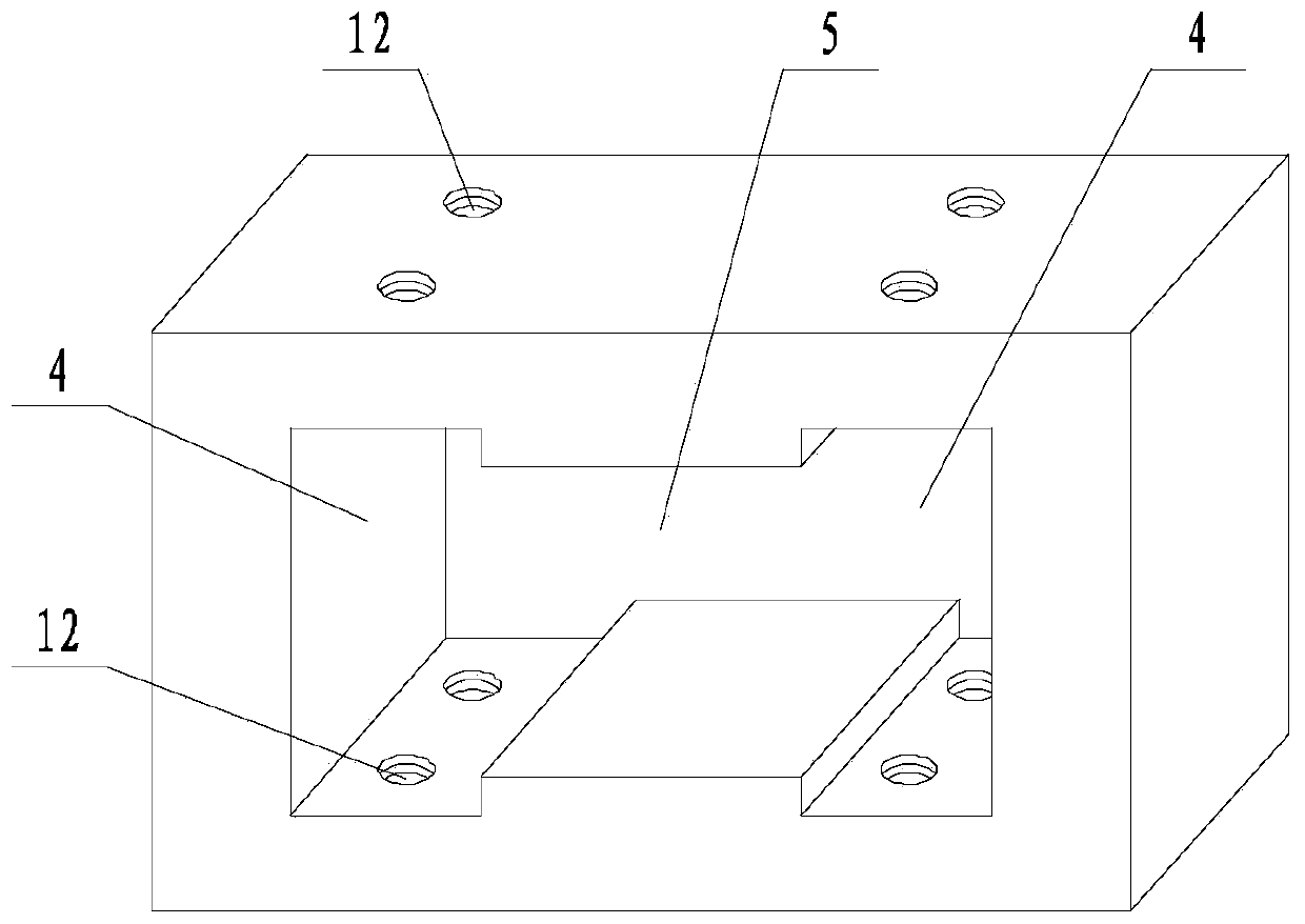
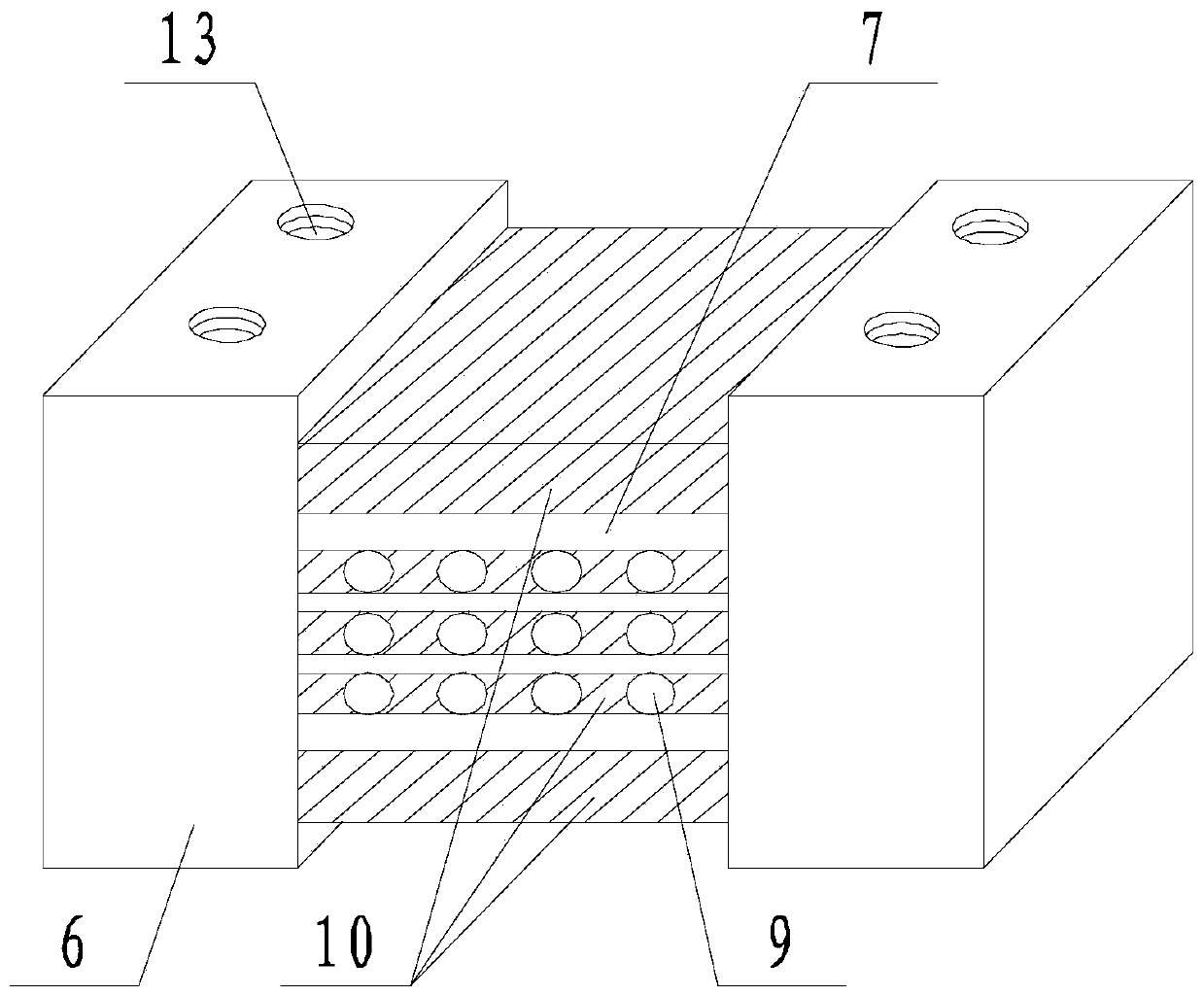
[0041] like Figure 1 to Figure 4 The connecting node of the stiffened concrete transfer column including the stiffened concrete transfer beam shown includes a stiffened concrete transfer column 1 and a stiffened concrete transfer beam 2, and the top fixed beam box 3 of the stiffened concrete transfer column 1, the The beam box 3 is provided with two through holes one 4 that run through the beam box 3 in the horizontal direction. It also runs through the beam box 3 in the horizontal direction; the stiffened concrete transfer beam 2 includes two steel pieces 1 6 respectively matched with the two through holes 4 , and the steel piece 2 7 is passed between the two steel pieces 6 Fixed connection, the thickness of the second steel part 7 is less than the height of the through hole two 5; several channels 8 are arranged in the second steel part 7, and a number of steel bars 9 pass through each channel, and the axes of the steel bars 9 are parallel On the axis of through hole 1 4 a...

Embodiment 2

[0048] like Figure 5 to Figure 8 The difference between this embodiment and Embodiment 1 of the connecting node of the stiffened concrete transfer column including the stiffened concrete transfer beam shown is that the cross-section of the through hole 4 in the vertical direction is a right-angled trapezoid, and the right-angled trapezoid The top side of the top side is longer than the bottom side, and the straight waist faces the direction of the second through hole 5; the cross section of the second through hole 5 in the vertical direction is square; the bottom surface of the second through hole 5 is higher than the bottom surface of the first through hole 4. The top surface of hole two 5 is lower than the top surface of through hole one 4 .

[0049] In addition, the beam box 3 is provided with two sets of first threaded through holes 12 facing each other on the upper and lower sides of the through hole one 4, and the first threaded through hole 12 facing the first threaded...


PUM


Abstract

The invention discloses a connection node and method for a reinforced concrete conversion column wrapping a reinforced concrete conversion beam. A beam box is fixed to the top of the reinforced concrete conversion column. Two through holes I penetrating through the beam box in the horizontal direction are formed in the beam box and communicate with each other through a through hole II. The reinforced concrete conversion beam comprises two shaped steel parts I which are matched with the two through holes I correspondingly. The two shaped steel parts are fixedly connected through a second shapedsteel part II. A plurality of channels are arranged in the shaped steel part II, and a plurality of reinforcing steel bars penetrate through each channel. Concrete is poured between the two shaped steel parts I, on two sides of the shaped steel part II and in the channels in the shaped steel part II. The reinforced concrete conversion beam further comprises a bolt, wherein the bolt is used for fixing the beam box and the shaped steel parts I. The connection node and method are used for solving the problems that in a reinforced concrete combination in the prior art, an enveloping structure ofa node position is complex and requires more consumables, and risks may happen to the end portion of a reinforced concrete beam or column in installation processes, and realizes the purposes of reducing the size of a reinforced concrete node and avoiding the risks of damage in connection processes.

Description

technical field [0001] The invention relates to the field of civil engineering, in particular to a connection node and a method for a stiffened concrete transfer column and a stiffened concrete transfer beam. Background technique [0002] At the bottom of the high-rise building structure, when the vertical components of the upper floor cannot be directly and continuously connected to the ground, a structural transfer layer should be set up, and the transfer structural members should be arranged in the structural transfer layer. The transfer structural member is to complete the structural form of the upper floor to the lower floor Structural member provided for transition or change of structural arrangement from upper story to lower story. The floor where the transfer structural components are located is called the transfer floor. The transfer floor supports the huge vertical load of the superstructure and is at the bottom of a high-rise building with complex internal forces ...

Claims


Application Information

Patent Timeline
Patent Type & Authority Applications(China)
IPC IPC(8): E04B1/21
CPCE04B1/215
Inventor 张学华罗彬郑勇刚杜文欢邹何川刘杰
Owner CITIC GUOAN CONSTR GRP CO LTD
Why Eureka
Try Eureka