Safety stage lamp holder

A light frame and stage technology, which is applied in lighting devices, outdoor lighting, lighting applications, etc., can solve problems such as injury, poor stability, and vibration damage of stage frames, and achieve good light and shadow effects, high stability, and strong safety.

Pending Publication Date: 2019-08-27
杭州友邦文化科技有限公司
View PDF0 Cites 2 Cited by
  • Summary
  • Abstract
  • Description
  • Claims
  • Application Information

AI Technical Summary

Problems solved by technology

In order to achieve this kind of performance effect, in modern stage design, it is often necessary to install a large number of stage lights. The fixed safety requirements of the stage lights are very high, and the stage lights need to be able to adjust the irradiation angle freely to ensure the diversity and controllability of the lights. Generally, large-scale universal control devices are used to control the irradiation direction of stage lights, but many fast-installed stage stands cannot support high-power lighting adjustment equipment, and are prone to vibration damage to the stage stand, and the stability is poor, and it is easy to cause equipment to fall. personal injury

Method used


Image

  • Safety stage lamp holder
  • Safety stage lamp holder

Examples


Embodiment 1

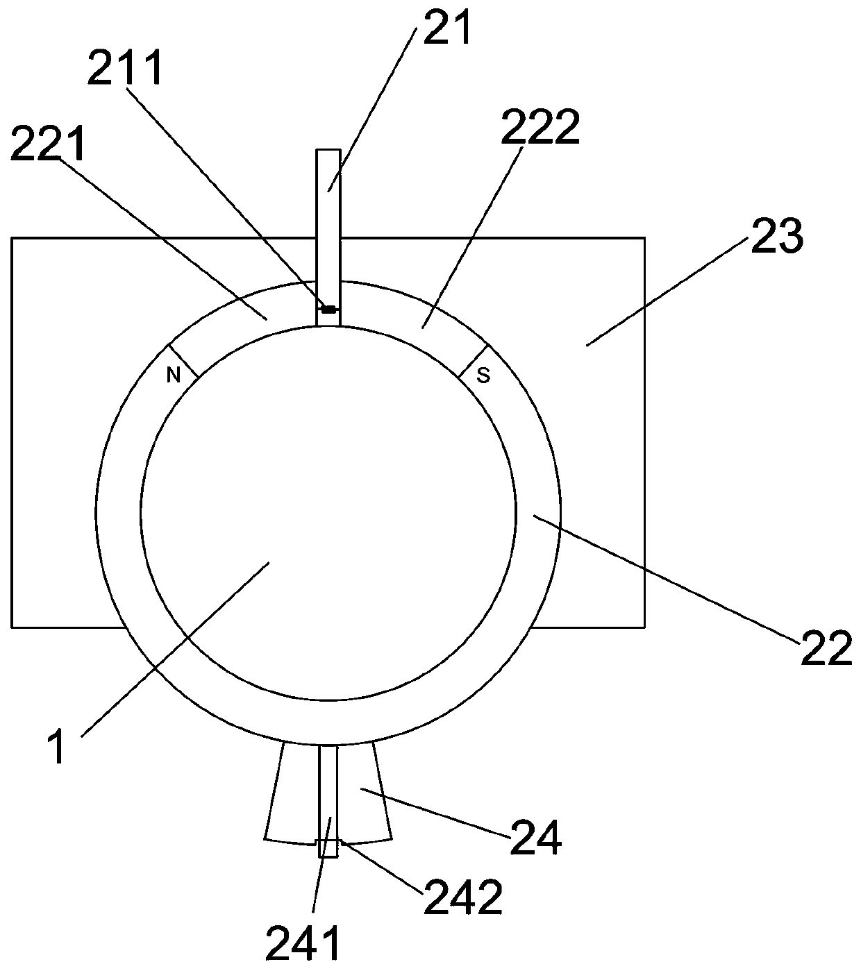
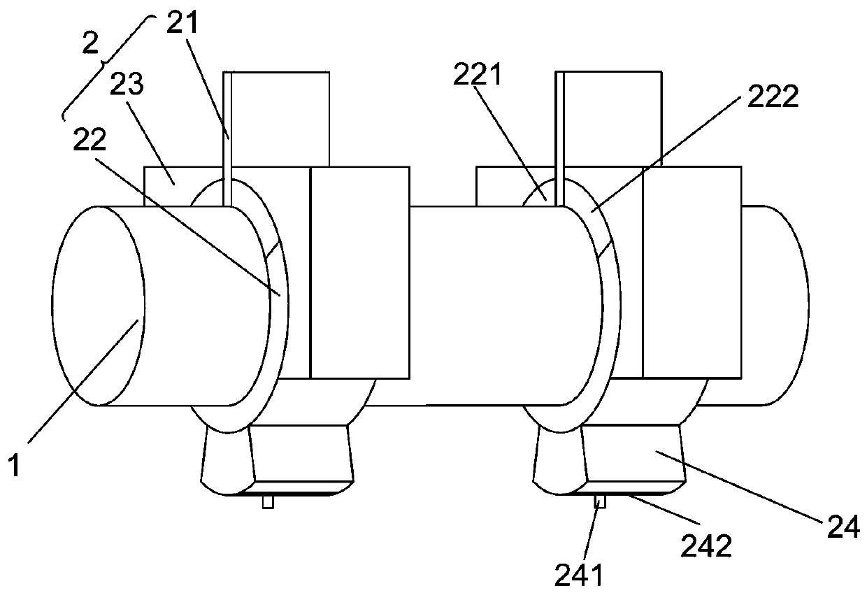
[0026] Embodiment one: if figure 1 , 2 As shown, it is only one of the embodiments of the present invention, a safety stage light stand, including a mounting column 1 and a light stand unit 2 arranged on the mounting column 1, and the light stand unit 2 includes a The fixed plate 21 fixedly connected to the column 1, the arc frame 22 arranged around the installation column 1 and the clamping block 23 for clamping the arc frame 22, one end of the arc frame 22 passes through the first limit The positioning block 221 is connected to the fixing plate 21, the other end of the arc frame 22 is connected to the other side of the fixing plate 21 through the second limiting block 222, and the lampshade 24 is connected under the arc frame 22, The arc frame 22 is a magnetic piece, and the fixed plate 21 is provided with an electromagnetic piece.

[0027] In the present invention, the installation column 1 is first fixedly installed, and then the lamp stand unit 2 is installed on the ins...

Embodiment 2

[0033] Embodiment two, still as figure 1 , 2 As shown, it is only one of the embodiments of the present invention. In order to make the light and shadow effect of a safety stage light stand of the present invention better and the degree of stability higher, the present invention also has the following design:

[0034] Firstly, the first limiting block 221 and the second limiting block 222 have the same size. Then both sides of the arc frame 22 are subjected to the same elastic force of the first limiting block 221 and the second limiting block 222. When the fixed plate 21 is vertically arranged and the electromagnetic part 211 is not energized, the left and right forces of the arc frame 22 are the same. , the arc frame 22 is also vertically arranged, and the angle of the lampshade 24 is also vertically downwardly arranged, which is more convenient for illuminating the stage theater.

[0035] Then, at least a part of the first limiting block 221 and the second limiting block ...


PUM


Abstract

The present invention provides a safety stage lamp holder and relates to the technical field of stage equipment; the safety stage lamp holder includes a mounting column, and a lamp holder unit disposed on the mounting column, wherein the lamp holder unit includes a fixing plate fixedly connected to the mounting column, an arc-shaped holder disposed around the mounting column, and a clamping blockfor clamping the arc-shaped holder; one end of the arc-shaped holder is connected to the fixing plate through a first stop block; the other end of the arc-shaped holder is connected to the other sideof the fixing plate through a second stop block; a lampshade is connected below the arc-shaped holder; the arc-shaped holder is a magnetic component; and an electromagnetic component is disposed on the fixing plate. The safety stage lamp holder of the present invention has the advantages of simple structure, high stability, strong safety, being difficult to damage, and good lighting effect, and may control a plurality of groups of stage lamps.

Description

technical field [0001] The invention relates to the technical field of stage equipment, [0002] In particular, the present invention relates to a safety stage light stand. Background technique [0003] With the enrichment of cultural life, people have higher and higher requirements for stage effects in performance activities. Many modern large-scale performance venues, etc., have installed various types of stage machinery and equipment in order to produce extraordinary special effects in performing arts. , It plays the role of finishing touch and magic touch in the stage performance of the repertoire. [0004] Stage lighting is an important part of the performance space. It is an art that performs a comprehensive visual environment lighting design on characters and specific scenes according to the development of the plot, and purposefully reproduces the design intention to the audience in a visual image. creation. In order to achieve this kind of performance effect, in m...

Claims


Application Information

Patent Timeline
Patent Type & Authority Applications(China)
IPC IPC(8): F21V21/14F21W131/105F21W131/406
CPCF21V21/14F21W2131/105F21W2131/406
Inventor 杨全明杨同焱
Owner 杭州友邦文化科技有限公司
Why Eureka
Try Eureka