
Plastic particle material saving structure

A plastic granule and material-saving technology, which is applied in the field of plastic granule processing, can solve problems such as easy splashing, and achieve the effects of ensuring stability, improving efficiency, and wide application range

Inactive Publication Date: 2019-08-30
CHONGQING JINGBANG HIGH MOLECULAR MATERIAL CO LTD
View PDF7 Cites 0 Cited by
  • Summary
  • Abstract
  • Description
  • Claims
  • Application Information

AI Technical Summary

Problems solved by technology

[0003] In order to solve the above problems, the present invention provides a material-saving structure for plastic granules, which solves the problem of easy splashing of plastic granules when they fall from the discharge pipe to the receiving pipe, and reduces the waste of plastic granules

Method used


Image

  • Plastic particle material saving structure
  • Plastic particle material saving structure
  • Plastic particle material saving structure

Examples


Embodiment 1

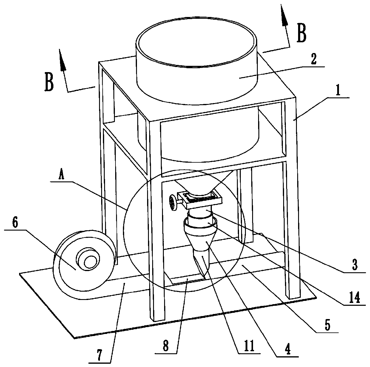
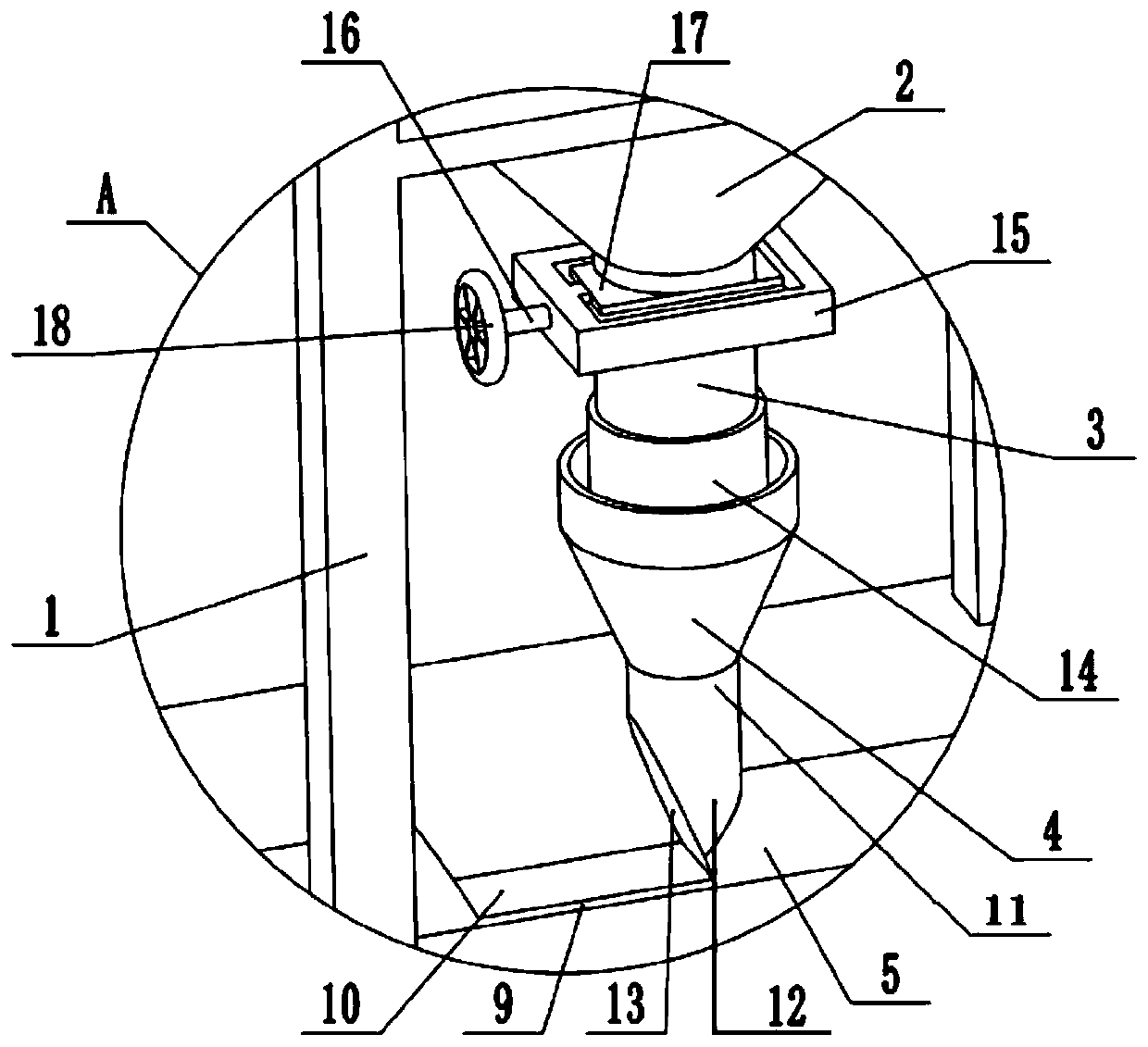
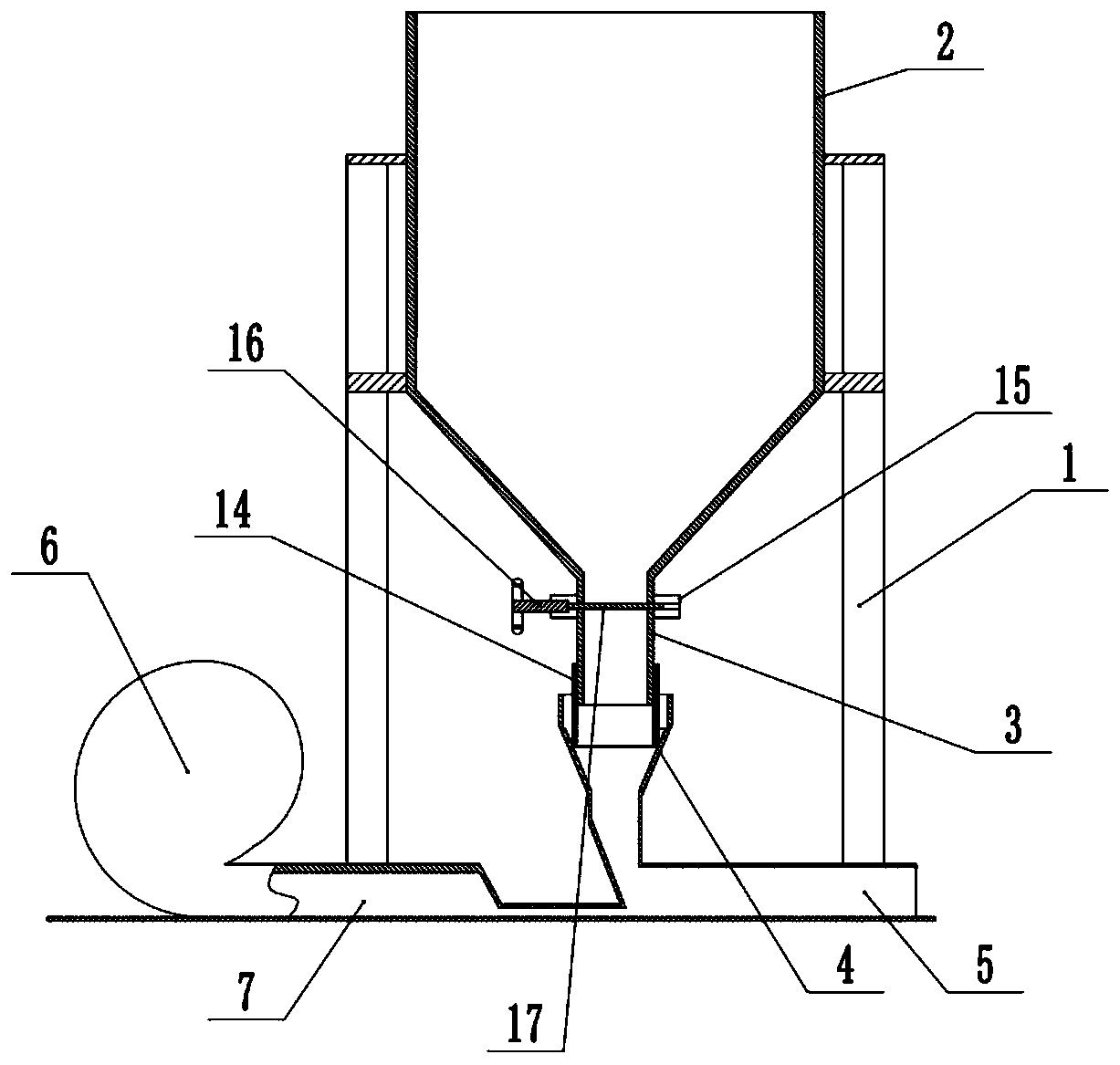
[0037] Embodiment one is basically as figure 1 , figure 2 , image 3 , Figure 4 and Figure 6 As shown, the material-saving structure of plastic particles includes a bracket 1 and a storage hopper 2 welded on the bracket 1. The storage hopper 2 is funnel-shaped as a whole and is used for temporarily storing plastic particles inside. The bottom of the storage hopper 2 is welded with a discharge pipe 3. The bottom of the discharge pipe 3 is provided with a receiving pipe 4 for receiving plastic particles falling from the discharge pipe 3, and the lower end of the receiving pipe 4 is connected with a horizontally arranged feeding pipe 5, and the left side of the feeding pipe 5 is provided for driving the feeding pipe. 5. The power mechanism for conveying plastic particles.

[0038] Such as figure 1 As shown, the power mechanism includes a fan 6 and an air guide pipe 7, the fan 6 is fixedly connected to the ground by bolts, the air guide pipe 7 is located between the fan 6 an...

Embodiment 2

[0047] Such as Figure 5 As shown, the difference between Embodiment 2 and Embodiment 1 is that: the air guide pipe 7 and the feeding pipe 5 are arranged obliquely in a state of left high and right low, so that when the gas blown by the fan 6 enters the feeding pipe 5, the flow direction of the gas and the connection The plastic particles falling from the pipe 4 have an inclination angle, and the plastic particles are easier to change the direction of movement under the blown by the inclined air flow, so that the plastic particles at the junction of the receiving pipe 4 and the delivery pipe 5 can be quickly blown away, and the plastic particles can be more effectively prevented. Blockage occurs at the junction of the receiving pipe 4 and the delivery pipe 5 .


PUM


Abstract

The invention relates to the technical field of plastic particle processing, in particular to a plastic particle material saving structure. The plastic particle material saving structure involves a storage hopper, the bottom of the storage hopper is fixedly connected with a discharging pipe, a bearing pipe right opposite to the discharging pipe is arranged below the discharging pipe, a material conveying pipe is connected to the bearing pipe, a power mechanism is arranged on the material conveying pipe, a movable sleeve is movably connected to the lower end of the discharging pipe, the lower end of the movable sleeve can extend into the bearing tube, and meanwhile, a speed regulation mechanism is arranged on the discharging tube. According to the plastic particle material saving structure,the relative positions of the movable sleeve and the discharging tube are adjusted, so that the lower end of the movable sleeve is in contact with the inner wall of the bearing tube, and the problemthat the plastic particles are prone to splashing and falling to cause waste due to the fact that the plastic particles fall into the bearing pipe from the discharging pipe is solved; and meanwhile, the speed regulation mechanism can adjust the falling speed of the plastic particles in the discharging pipe, the production rhythm of the subsequent screening process is effectively controlled, when ascreening mechanism breaks down, discharging is stopped at the discharging pipe, so that the fault is convenient to remove.

Description

technical field [0001] The invention relates to the technical field of plastic particle processing, in particular to a material-saving structure of plastic particles. Background technique [0002] In the processing of plastic granules, it generally needs to go through the preparation before batching-batch weighing-kneading-extrusion granulation-cooling-screening-bagging and other processing procedures. In the prior art, between extrusion granulation and screening processes, Generally, a storage hopper is used to temporarily store the plastic particles that have been formed, and then the plastic particles in the storage hopper are transported to the screening device by a power mechanism. This transportation process is completed in the delivery pipe, and its specific structure is as follows: The bottom of the hopper is provided with a discharge pipe, and the lower part of the discharge pipe is provided with a receiving pipe connected with the feeding pipe. The plastic particle...

Claims


Application Information

Patent Timeline
Patent Type & Authority Applications(China)
IPC IPC(8): B29C48/28B29C48/04
CPCB29C48/04B29C48/28
Inventor 王孝海
Owner CHONGQING JINGBANG HIGH MOLECULAR MATERIAL CO LTD
Learn More