Grille device applied to prefabricated pump station
A grid and pumping station technology, applied in the field of prefabricated pumping stations, to achieve the effect of reasonable structure and scientific layout
- Summary
- Abstract
- Description
- Claims
- Application Information
AI Technical Summary
Problems solved by technology
Method used
Image
Examples
Embodiment approach
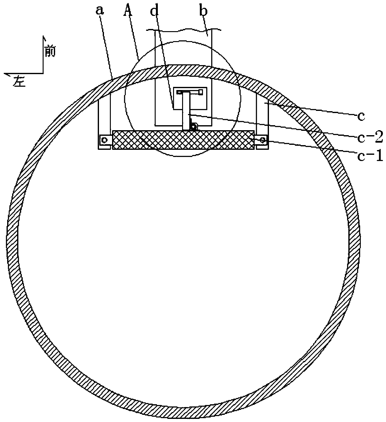
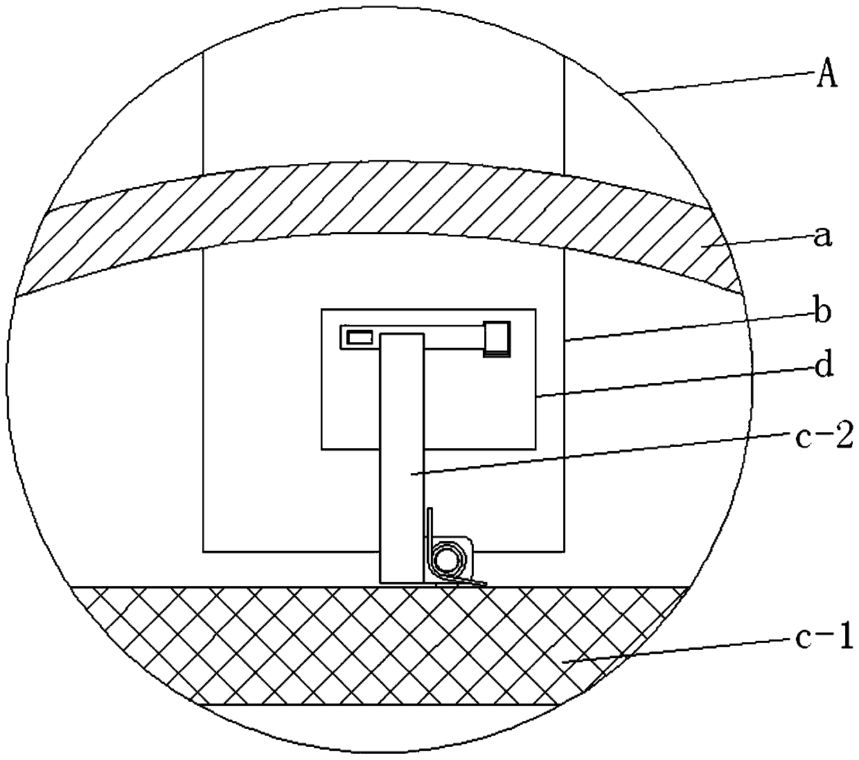
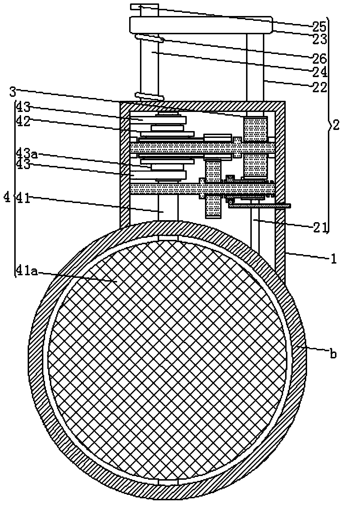
[0068] The trigger device 2 goes down when the trigger lever c-2 is pressed down and resets automatically under normal conditions. The trigger device 2 includes a trigger mandrel located at the right side of the upper end of the water inlet b and corresponding to the grille shell 1 21. The sliding sleeve 22 slidably sleeved on the trigger mandrel 21, the rear end of the sliding sleeve 22 is formed with an input rack, and the upper end of the sliding sleeve 22 runs through the upper end of the grid housing 1 Setting, the upper end of the sliding sleeve 22 is formed with a trigger bar 23 to the left, and the trigger device 2 also includes a fixed upper shaft arranged on the left side of the upper end surface of the grille shell 1 and passing through the trigger bar 23 24, the upper end of the fixed upper shaft 24 is formed with an upper limit block 25, and the fixed upper shaft 24 is also provided with a first compression spring 26 between the trigger cross bar 23 and the upper e...
Embodiment 1
[0093] Example 1, under normal conditions, the basket body c-1 filters the water inlet pipe b:
[0094] Under normal conditions, the basket body c-1 and the trigger lever c-2 press down on the trigger device 2, and the trigger bar 23 and the sliding sleeve 22 overcome the force of the first compression spring 26 and move down;
[0095] The input rack on the rear end surface of the sliding sleeve 22 acts on the right large gear 31c to make it rotate, and the right large gear 31c drives the right small gear 32c and the left large gear 32b to rotate. The left large gear 32b finally drives the left small gear 31b and the worm screw 33 to rotate;
[0096] The worm 33 drives the worm wheel 42, the action circular shaft 41, and the spare grille body 41a to rotate. Under normal conditions, the plane of the spare grille body 41a is consistent with the water flow direction of the water inlet pipe b, so as to avoid damage to the miscellaneous elements in the water inlet pipe b. Objects ...
Embodiment 2
[0097] Embodiment 2, when the basket body c-1 is lifted up for cleaning, the spare grille body 41a filters the water inlet pipe:
[0098] The basket body c-1 has accumulated a lot of sundries after being used for a period of time, and needs to be lifted to the outside of the cylinder a of the pump station for cleaning.
[0099] Once the basket body c-1 and the trigger lever c-2 go up, the first pressure spring 26 acts on the trigger bar 23 and the sliding sleeve 22 to go up;
[0100] The input rack at the rear end of the sliding sleeve 22 acts on the right large gear 31c to make it rotate in reverse, and the right large gear 31c drives the right small gear 32c and the left large gear 32b to rotate in reverse , the left large gear 32b finally drives the left small gear 31b and the worm 33 to rotate in reverse;
[0101] The worm 33 drives the worm gear 42, the action circular shaft 41, and the spare grille body 41a to rotate in the opposite direction. Under normal conditions, t...
PUM
 Abstract
Description
Claims
Application Information
 - R&D
- Intellectual Property
- Life Sciences
- Materials
- Tech Scout
- Unparalleled Data Quality
- Higher Quality Content
- 60% Fewer Hallucinations
Browse by: Latest US Patents, China's latest patents, Technical Efficacy Thesaurus, Application Domain, Technology Topic, Popular Technical Reports.
© 2025 PatSnap. All rights reserved.Legal|Privacy policy|Modern Slavery Act Transparency Statement|Sitemap|About US| Contact US: help@patsnap.com


