
Vortex machine and electromagnetic mechanism thereof, and electromagnetic air gap optimization method of electromagnetic mechanism

An electromagnetic mechanism and electromagnetic technology, applied in the direction of machines/engines, rotary piston machines, rotary piston engines, etc., can solve the problems of non-adjustable pressure, residual resultant force, and inability to realize automatic compensation of axial clearance, etc., and achieve low contact force , high sealing effect

Active Publication Date: 2019-08-30
ZHEJIANG UNIVERSITY OF SCIENCE AND TECHNOLOGY
View PDF5 Cites 6 Cited by
  • Summary
  • Abstract
  • Description
  • Claims
  • Application Information

AI Technical Summary

Problems solved by technology

[0004] 1) Spring back pressure scheme: install a spring on the back of the volute (generally a moving volute). This structure is relatively convenient to implement, but the pressure cannot be adjusted, and the friction between the spring and the volute under high pressure has a greater impact on the life of the material. Big challenges will also bring problems such as friction loss on the spring working surface;
[0005] 2) Thrust bearing scheme: install a thrust bearing on the back of the scroll to realize mechanical positioning; adopt this structure to fix the axial position of the scroll, and cannot realize automatic compensation of the axial clearance, and it is difficult to achieve a balance between sealing and small pressure. Balanced, and it is difficult to find a suitable thrust bearing in many occasions (such as the field of high pressure machines);
[0006] 3) Gas back pressure chamber scheme: A certain gas pressure is applied on the back of the vortex, and the pressure in the back pressure chamber changes with the angle similar to the change of gas in the chamber. Although this structure can offset a relatively large amount of gas in the chamber Outward axial pressure, but the resultant force of the two still has a large proportion of residue, and the resultant force is related to the angle, there are still problems of large friction or leakage, which is not conducive to the stable rotation of the scroll;
The electromagnetic air gap of the actual electromagnetic mechanism is affected by two main factors: 1) Because of the internal design of multiple parts, and the design air gap is generally set between 0.05 mm and 0.1 mm, errors in assembly are unavoidable and small The error will occupy a large proportion in such a small scale, which will seriously affect the control effect; 2) In the operation of the scroll, the dynamic and static scrolls are in contact with each other for a long time, and wear is unavoidable. These wears also need to be optimized and corrected regularly
[0010] Based on the above reasons, in the electromagnetic control system of the axial gas force of the scroll machine, the control error caused by the electromagnetic air gap seriously affects the control accuracy. Therefore, it is necessary to provide an electromagnetic air gap optimization method to reduce the actual electromagnetic air gap. The effect of clearance on control accuracy

Method used

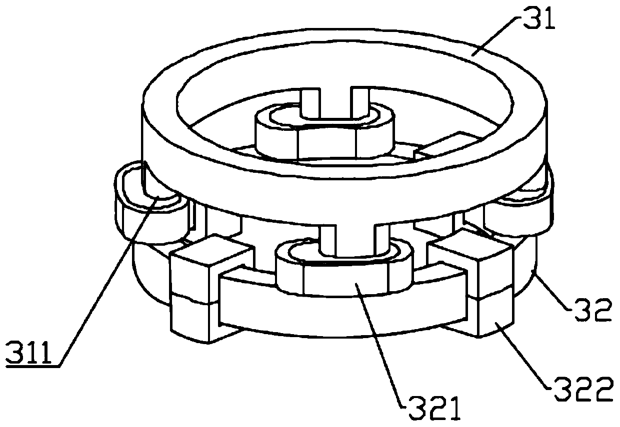
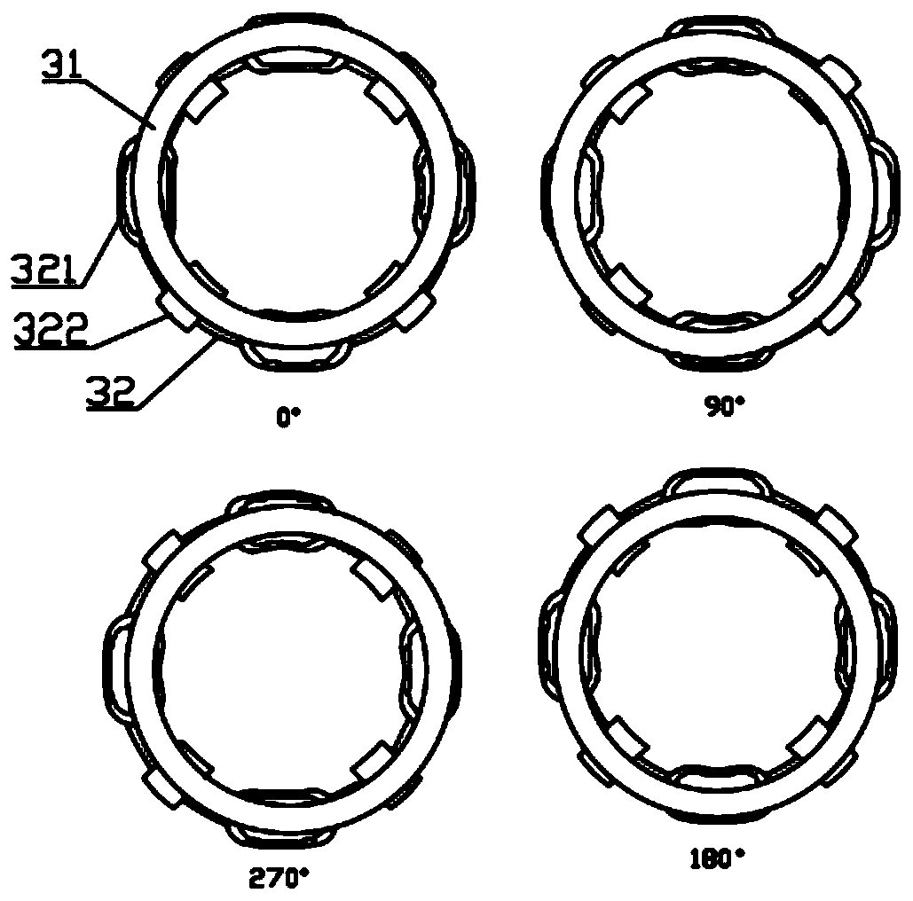
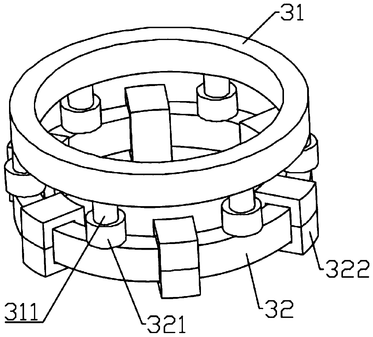

Image

  • Vortex machine and electromagnetic mechanism thereof, and electromagnetic air gap optimization method of electromagnetic mechanism
  • Vortex machine and electromagnetic mechanism thereof, and electromagnetic air gap optimization method of electromagnetic mechanism
  • Vortex machine and electromagnetic mechanism thereof, and electromagnetic air gap optimization method of electromagnetic mechanism

Examples


Embodiment Construction

[0064] The present invention will be further described below in conjunction with the accompanying drawings and embodiments.

[0065] It should be pointed out that the following detailed description is exemplary and intended to provide further explanation to the present application. Unless defined otherwise, all technical and scientific terms used herein have the same meaning as commonly understood by one of ordinary skill in the art to which this application belongs.

[0066] It should be noted that the terminology used here is only for describing specific implementations, and is not intended to limit the exemplary implementations according to the present application. As used herein, unless the context clearly dictates otherwise, the singular is intended to include the plural, and it should also be understood that when the terms "comprising" and / or "comprising" are used in this specification, they mean There are features, steps, operations, means, components and / or combinatio...


PUM


Abstract

The invention discloses a vortex machine and an electromagnetic mechanism thereof, and an electromagnetic air gap optimization method of the electromagnetic mechanism. The electromagnetic air gap optimization method comprises the following steps of (A), presetting the electromagnetic air gap value sigma0, and combining with the target pressure P0 to generate a 'rotating angle-current' relationshipcurve; (B), detecting a rotating angle value alpha(t), determining the current value of an excitation component according to the 'rotating angle-current' relationship curve, and adjusting the axial electromagnetic force; (C), detecting a current exhaust pressure P(t) and comparing the exhaust pressure P(t) with the target pressure P0, and reassigning the electromagnetic air gap sigma0 according to the comparison result; and (D), according to the electromagnetic air gap sigma0, redetermining the rotating angle-current relationship curve, combining with the current rotating angle value alpha(t)of a dynamic vortex disc to determine the current value of the excitation component, and adjusting the axial electromagnetic force. The electromagnetic air gap optimization method is used to correctthe assembly error and the electromagnetic axial force error caused by the electromagnetic air gap error caused by wear in the process of using.

Description

technical field [0001] The invention relates to the axial gas force control technology of a vortex machine, and provides a vortex machine and its electromagnetic mechanism and an electromagnetic air gap optimization method of the electromagnetic mechanism, which are used to correct assembly errors and electromagnetic air gaps caused by wear during use The electromagnetic force error caused by the error. Background technique [0002] A scroll machine is a fluid machine that achieves gas compression by means of volume changes. Its internal structure mainly includes a fixed scroll, a movable scroll, a bracket, an eccentric shaft, and an anti-rotation mechanism. Among them, the movable scroll and the fixed scroll Eccentric setting, as the movable scroll rotates under the drive of the eccentric shaft, the gas between the movable scroll and the fixed scroll will gather in the middle or diffuse to the periphery, thus realizing the function of compressor or expander. [0003] Compa...

Claims


Application Information

Patent Timeline
Patent Type & Authority Applications(China)
IPC IPC(8): F04C28/00F04C28/28F04C29/00F04C18/02F01C20/00F01C20/28F01C21/00F01C1/02
CPCF01C1/0215F01C20/00F01C20/28F01C21/003F04C18/0215F04C28/00F04C28/28F04C29/0021
Inventor 蔡炯炯程楷一张汪洋刘峰王子辉
Owner ZHEJIANG UNIVERSITY OF SCIENCE AND TECHNOLOGY
Learn More