
Vortex machine, electromagnetic mechanism thereof and control method of electromagnetic mechanism

An electromagnetic mechanism and control method technology, applied in the direction of machines/engines, rotary piston machinery, mechanical equipment, etc., can solve the problems of increasing the plane area of ​​the movable scroll machine, unadjustable pressure, tight contact wear and more heat dissipation, etc., to achieve The effect of high precision dynamic active control, low contact force and high sealing performance

Active Publication Date: 2019-07-12
ZHEJIANG UNIVERSITY OF SCIENCE AND TECHNOLOGY
View PDF5 Cites 5 Cited by
  • Summary
  • Abstract
  • Description
  • Claims
  • Application Information

AI Technical Summary

Problems solved by technology

[0004] 1) Spring back pressure scheme: install a spring on the back of the volute (generally a moving volute). This structure is relatively convenient to implement, but the pressure cannot be adjusted, and the friction between the spring and the volute under high pressure has a greater impact on the life of the material. Big challenges will also bring problems such as friction loss on the spring working surface;
[0005] 2) Thrust bearing scheme: install a thrust bearing on the back of the scroll to realize mechanical positioning; adopt this structure to fix the axial position of the scroll, and cannot realize automatic compensation of the axial clearance, and it is difficult to achieve a balance between sealing and small pressure. Balanced, and it is difficult to find a suitable thrust bearing in many occasions (such as the field of high pressure machines);
[0006] 3) Gas back pressure chamber scheme: A certain gas pressure is applied on the back of the vortex, and the pressure in the back pressure chamber changes with the rotation angle similar to the change of gas in the chamber. Outward axial pressure, but the resultant force of the two still has a large proportion of residue, and the resultant force is related to the rotation angle, there are still problems of large friction or leakage, which is not conducive to the stable rotation of the scroll;
In the scroll compressor with this structure, the axial gas force on the upper and lower scroll bodies of the movable scroll is equal in magnitude and opposite in direction, so the axial gas force on the movable scroll is automatically fully balanced, But from a theoretical point of view of this structure, the axial gas forces on the two moving scrolls of the double scroll body can subtly cancel each other out; The assembly accuracy of the contact surface is difficult to control, the tight contact will cause more wear and heat dissipation, and the loose contact will easily leak
If it is a fixed installation, it is difficult to adjust the state of the contact surface due to wear and tear after working for a long time; if it is an axial floating installation, obviously it can only be realized by the axial floating of the static scroll, which also requires back pressure control, and the two scrolls Backpressure adds complexity
[0008] In addition, in the article "Research on Key Technology of Oil-free Scroll Compressor" (Shenyang University of Technology Dou Rutong et al., 2017.06.02), an oil-free compressor using planar electromagnetic drive is proposed. force control scheme, and adopts electromagnetic force control in axial gas force control. This scheme adopts a distributed electromagnetic force structure at three points, which can effectively solve the above-mentioned contact friction problem, but it does not provide a specific control method, and This scheme greatly increases the area on the plane of the movable scroll machine, thereby significantly increasing the moment of inertia and reducing the dynamic performance of the scroll system; this structure needs to use force feedback signals to control the electromagnetic force, but for such gaps The high-precision mechanism with less than 10 wires, the method of installing the force feedback device increases the structural complexity, installation difficulty and cost, and also reduces the reliability and life of the system; when used as an expander, only gas is used to drive the scroll to rotate It is especially difficult to increase speed and improve work efficiency
[0009] Based on the above, in the existing axial gas force control scheme of the scroll machine, the influence of the axial gas force cannot be completely offset, or the dynamic performance of the scroll machine is reduced after the axial gas force is offset, and there is no disclosure Corresponding control method, therefore, it is necessary to provide a control method of the electromagnetic mechanism for controlling the axial gas force of the vortex machine, and combine this method with the electromagnetic mechanism for controlling the axial gas force of the vortex machine to realize the vortex Low contact force during the working process of the machine while ensuring high sealing performance

Method used

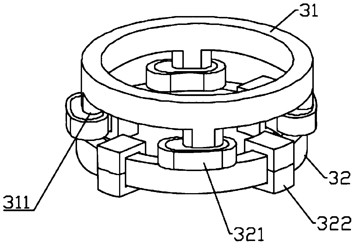
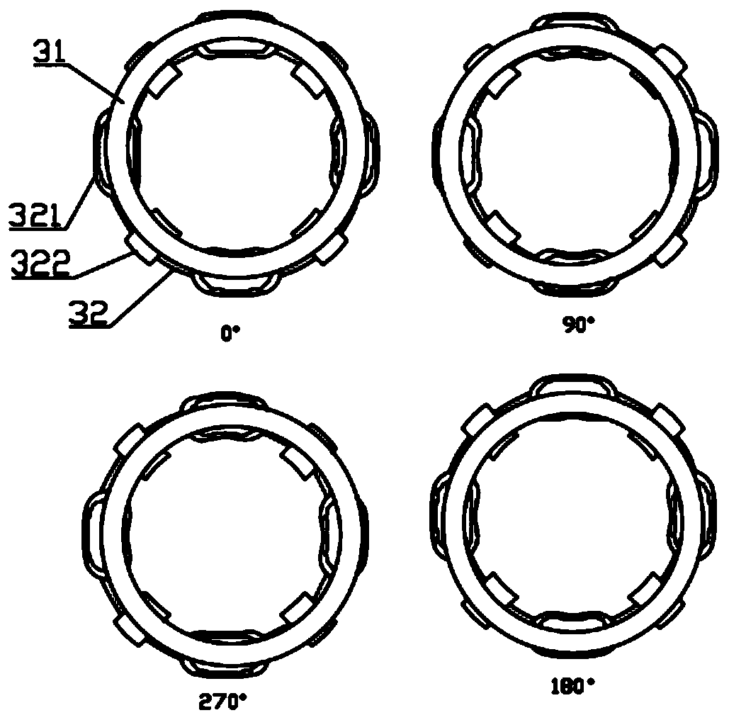
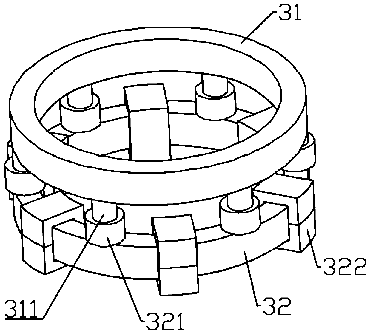

Image

  • Vortex machine, electromagnetic mechanism thereof and control method of electromagnetic mechanism
  • Vortex machine, electromagnetic mechanism thereof and control method of electromagnetic mechanism
  • Vortex machine, electromagnetic mechanism thereof and control method of electromagnetic mechanism

Examples


Embodiment Construction

[0056] The present invention will be further described below in conjunction with the accompanying drawings and embodiments.

[0057] It should be pointed out that the following detailed description is exemplary and intended to provide further explanation to the present application. Unless defined otherwise, all technical and scientific terms used herein have the same meaning as commonly understood by one of ordinary skill in the art to which this application belongs.

[0058] It should be noted that the terminology used here is only for describing specific implementations, and is not intended to limit the exemplary implementations according to the present application. As used herein, unless the context clearly dictates otherwise, the singular is intended to include the plural, and it should also be understood that when the terms "comprising" and / or "comprising" are used in this specification, they mean There are features, steps, operations, means, components and / or combinatio...


PUM


Abstract

The invention discloses a vortex machine, an electromagnetic mechanism thereof and a control method of the electromagnetic mechanism. The control method comprises the steps of (a) acquiring an angle-current relation curve according to the current exhaust pressure P(t) and the preset electromagnetic air gap sigma<0>; (b) adjusting the current I in an excitation component to enable the axial electromagnetic force in the electromagnetic mechanism to offset the axial air force; (c) judging whether the vortex machine is in a stable operation state or not, if yes, executing the step (d), and if not,executing the steps from (a), (b) and (c); and (d) adjusting the current I(t) in the excitation component according to the angle-current relation curve combined with the current vortex plate angle alpha(t) and then returning to the step (c). Through the method, the requirements for low contact force and high sealing performance between a moving vortex plate and a static vortex plate can be realized.

Description

technical field [0001] The invention relates to the axial gas force control technology of a scroll machine, and provides a scroll machine, an electromagnetic mechanism and a control method thereof, which are used for adjusting and balancing the contact force between a movable scroll and a static scroll in the scroll machine. Background technique [0002] A scroll machine is a fluid machine that achieves gas compression by means of volume changes. Its internal structure mainly includes a fixed scroll, a movable scroll, a bracket, an eccentric shaft, and an anti-rotation mechanism. Among them, the movable scroll and the fixed scroll Eccentric setting, as the movable scroll rotates under the drive of the eccentric shaft, the gas between the movable scroll and the fixed scroll will gather in the middle or diffuse to the periphery, thus realizing the function of compressor or expander. [0003] Compared with other compressors / expanders, the scroll machine has the advantages of le...

Claims


Application Information

Patent Timeline
Patent Type & Authority Applications(China)
IPC IPC(8): F04C28/00F04C29/00F04C18/02
CPCF04C18/0215F04C28/00F04C29/0021
Inventor 蔡炯炯张汪洋祝亮蒋惠忠王子辉
Owner ZHEJIANG UNIVERSITY OF SCIENCE AND TECHNOLOGY
Learn More