
Low-power-consumption electric equipment, electricity utilization system and power supply method and device of electric equipment

A technology of electrical equipment and electrical system, applied in the field of power supply of electrical systems and electrical equipment, and low-power electrical equipment, can solve problems such as increasing the cost of controllers, achieve saving power consumption, reduce economic pressure, Effect of reducing power consumption cost

Pending Publication Date: 2019-08-30
GREE ELECTRIC APPLIANCES INC
View PDF0 Cites 2 Cited by
  • Summary
  • Abstract
  • Description
  • Claims
  • Application Information

AI Technical Summary

Problems solved by technology

The air conditioner controller is generally powered by AC-DC power supply or DC-DC, etc. During the operation of the air conditioner controller, part of the electric energy input from the power supply is used by the controller as active power, and part of it will be used in the form of reactive power and heat energy. Consumed; on the one hand, this part of the heat energy brings a certain bottleneck problem to the normal development of the controller, on the other hand, in order to ensure the stable operation of the controller, it is necessary to perform additional heat dissipation treatment on the controller, which undoubtedly increases the controller’s cost

Method used


Image

  • Low-power-consumption electric equipment, electricity utilization system and power supply method and device of electric equipment
  • Low-power-consumption electric equipment, electricity utilization system and power supply method and device of electric equipment
  • Low-power-consumption electric equipment, electricity utilization system and power supply method and device of electric equipment

Examples


Embodiment Construction

[0040] In order to make the purpose, technical solution and advantages of the present invention clearer, the technical solution of the present invention will be described in detail below. Apparently, the described embodiments are only some of the embodiments of the present invention, but not all of them. Based on the embodiments of the present invention, all other implementations obtained by persons of ordinary skill in the art without making creative efforts fall within the protection scope of the present invention.

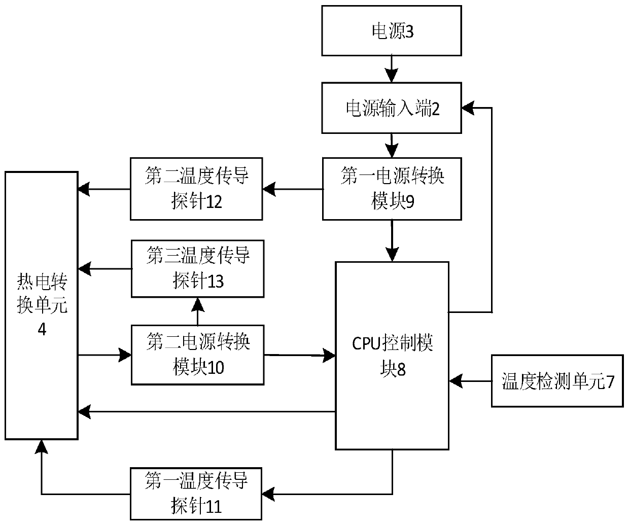
[0041] figure 1 It is a schematic structural diagram provided by Embodiment 1 of the low-power consumption electrical equipment of the present invention.

[0042] Such as figure 1 As shown, the low power consumption electrical equipment of this embodiment includes:

[0043] The power consumption unit 1 is used to work after being supplied with power, and to generate heat energy during work;

[0044] The power input terminal 2 is used to connect to the power ...


PUM


Abstract

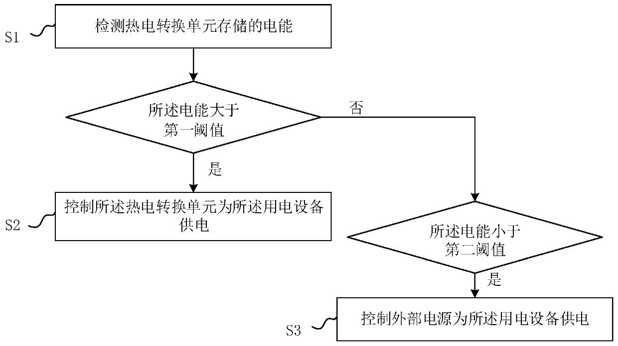
The invention relates to low-power-consumption electric equipment, an electricity utilization system and a power supply method and device of the electric equipment. The electric equipment comprises anelectricity utilization unit which is used for working after being powered and generating heat energy during working; a thermoelectric conversion unit which is used for converting the heat generatedby the electricity utilization unit into electric energy and storing the electric energy; a control unit which is used for controlling the thermoelectric conversion unit to supply power to the electric equipment when the electric energy stored in the thermoelectric conversion unit is greater than a first threshold value and controlling a power supply input end to be accessed to a power supply to supply power to the electric equipment when the electric energy stored in the thermoelectric conversion unit is less than a second threshold. According to the invention, the thermoelectric conversion unit converts heat energy dissipated by the electricity utilization unit into electric energy for reuse by electric equipment; the problem that the operation stability is influenced due to the temperature rise of the electric equipment caused by long-term operation of the electric equipment is solved, and reduction of the power consumption cost of the electric equipment is facilitated; the power consumption is reduced; and the economic pressure of a user is reduced.

Description

technical field [0001] The invention relates to the technical field of power supply control, in particular to a low-power consumption electrical equipment, an electrical system, and a power supply method and device for the electrical equipment. Background technique [0002] The traditional air-conditioning system controller is directly powered by the power supply. During the long-term operation of the air-conditioning system, the power consumption is huge, which puts huge economic pressure on many air-conditioning users. The air conditioner controller is generally powered by AC-DC power supply or DC-DC, etc. During the operation of the air conditioner controller, part of the electric energy input from the power supply is used by the controller as active power, and part of it will be used in the form of reactive power and heat energy. Consumed; on the one hand, this part of the heat energy brings a certain bottleneck problem to the normal development of the controller, on the...

Claims


Application Information

Patent Timeline
Patent Type & Authority Applications(China)
IPC IPC(8): H02J7/34H02J7/32
CPCH02J7/34H02J7/32
Inventor 叶唤涛李陈杰刘泉洲李忠正玉维友叶铁英李玉发唐玉龙赖东锋邓忠文
Owner GREE ELECTRIC APPLIANCES INC
Learn More