
Fire extinguishing element for flameless explosion pressure relief device

A pressure relief device, flameless technology, used in packaging, fire rescue, transportation and packaging, etc., can solve the problems of reduced blocking performance, loss of explosion pressure relief, and increased blocking effect, achieving high pressure relief efficiency and preventing flames. The effect of spreading

Pending Publication Date: 2019-09-03
HUILE INSFORD ENVIRONMENTAL SAFETY RES INST (SUZHOU) CO LTD +2
View PDF0 Cites 0 Cited by
  • Summary
  • Abstract
  • Description
  • Claims
  • Application Information

AI Technical Summary

Problems solved by technology

When the fire extinguishing element has less filling and larger pores, the pressure relief efficiency is higher, but the resistance of the element to airflow and dust is also reduced, and the flame is easier to pass through, resulting in a decrease in fire extinguishing performance. When the flame passes through the fire extinguishing element , it will cause a secondary explosion or cause personal and property losses; when the fire extinguishing element has more fillers and smaller pores, the fire extinguishing performance is higher, but due to the increased resistance of the element to the flame, dust and hot air flow, it may lead to being extinguished. The pressure in the protective container rises, which may cause the container to rupture completely and lose the effect of explosion pressure relief in serious cases
However, the existing fire extinguishing elements do not comprehensively consider the two parameters of the amount of filler and the size of the pores, so that both pressure relief efficiency and fire extinguishing performance cannot be considered at the same time, and high fire extinguishing performance and pressure relief efficiency cannot be guaranteed at the same time.

Method used


Image

  • Fire extinguishing element for flameless explosion pressure relief device
  • Fire extinguishing element for flameless explosion pressure relief device
  • Fire extinguishing element for flameless explosion pressure relief device

Examples


Embodiment Construction

[0022] The present invention will be further described below in conjunction with the accompanying drawings and specific embodiments.

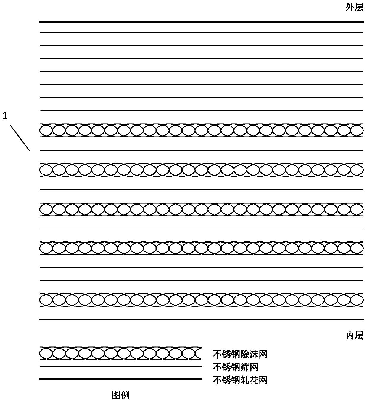
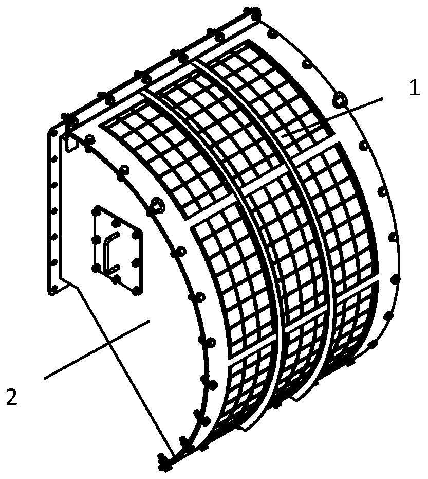
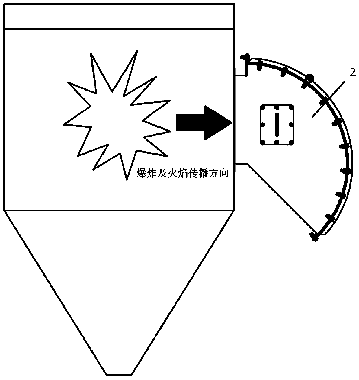
[0023] Such as figure 1 As shown, it is a structural schematic diagram of the fire extinguishing element used in the flameless explosion pressure relief device of the present invention. The fire extinguishing element 1 for flameless explosion pressure relief device 2 of the present invention is characterized in that:

[0024] The first layer and the 42nd layer of the fire extinguishing element 1 are all stainless steel embossed meshes with a wire diameter of 3mm and an aperture of 50mm;

[0025] The 2nd to 7th layers, the 10th to 15th layers, the 17th to 20th layers, the 22nd to 27th layers, and the 29th to 34th layers of the fire extinguishing element 1 are all stainless steel defoaming nets;

[0026] The 8th, 16th, 21st, 35th to 36th, 38th, and 40th to 41st layers of the fire extinguishing element 1 are all 15-mesh stainless steel mesh;

...


PUM

PropertyMeasurementUnit
diameteraaaaaaaaaa
pore sizeaaaaaaaaaa

Abstract

The invention relates to the technical field of dust explosion pressure relief, and provides a fire extinguishing element for a flameless explosion pressure relief device. The fire extinguishing element is characterized in that the 1st layer and the 42nd layer of the fire extinguishing element are stainless steel crimped wire meshes having a wire size of 3 mm and a pore size of 50 mm, the layers 2-7, 10-15, 17-20, 22-27 and 29-34 of the fire extinguishing element are stainless steel antifoaming nets, the 8th layer, the 16th layer, the 21st layer, the layers 35-36, the 38th layer and the layers40-41 of the fire extinguishing element are 15 mesh stainless steel sieve meshes, the 9th layer and the 28th layer of the fire extinguishing element are 200 mesh stainless steel sieve meshes, and the37th layer and the 39th layer of the fire extinguishing element are 150 mesh stainless steel sieve meshes. According to the present invention, the fire extinguishing element can effectively extinguish the flame generated by explosion, and maintains high pressure relief efficiency.

Description

technical field [0001] The invention relates to the technical field of dust explosion pressure relief, in particular to a fire extinguishing element used in a flameless explosion pressure relief device. Background technique [0002] The flameless explosion pressure relief device is a protective device that can be used for indoor dust explosion pressure relief, and is composed of a pressure relief element and a fire extinguishing element. The working principle of the fire extinguishing element is to extinguish the flame by forming many pores smaller than the maximum safe gap for flame propagation through the porous multilayer structure of the element, and at the same time capture larger particles of dust, and through a large number of fillers, absorb the heat of the flame, reduce the air flow and The temperature of the dust can be safely released to the surrounding environment to safely release the shock wave and hot air flow generated by the explosion, reducing the damage to...

Claims


Application Information

Patent Timeline
Patent Type & Authority Applications(China)
IPC IPC(8): B32B15/18B32B15/02B32B15/04B32B7/08B65D90/32A62C3/04
CPCB32B15/18B32B15/02B32B15/043B32B7/08B65D90/325A62C3/04
Inventor 钟圣俊苗楠陈然蒋关宇王娜娜刘洪洋项广帅
Owner HUILE INSFORD ENVIRONMENTAL SAFETY RES INST (SUZHOU) CO LTD
Learn More