Automatic conveying mechanism for conveying carbon rod

A technology of automatic feeding and driving mechanism, which is applied in the direction of conveyor, transportation and packaging, etc.

Inactive Publication Date: 2019-09-03
江苏双辉环境科技有限公司
View PDF7 Cites 2 Cited by
  • Summary
  • Abstract
  • Description
  • Claims
  • Application Information

AI Technical Summary

Problems solved by technology

[0004] The technical problem to be solved by the present invention is: in order to solve the problem that the feeding and unloading of the grinder needs to be realized by manpower in the prior art

Method used


Image

  • Automatic conveying mechanism for conveying carbon rod
  • Automatic conveying mechanism for conveying carbon rod
  • Automatic conveying mechanism for conveying carbon rod

Examples


Embodiment Construction

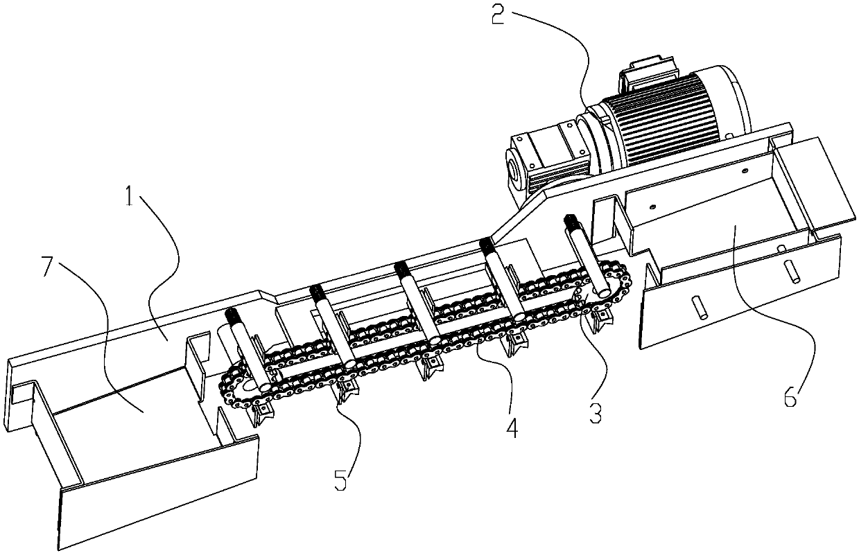
[0029] Such as Figure 1~8 As shown, the present invention provides a kind of automatic feeding mechanism for conveying carbon rods, comprising:

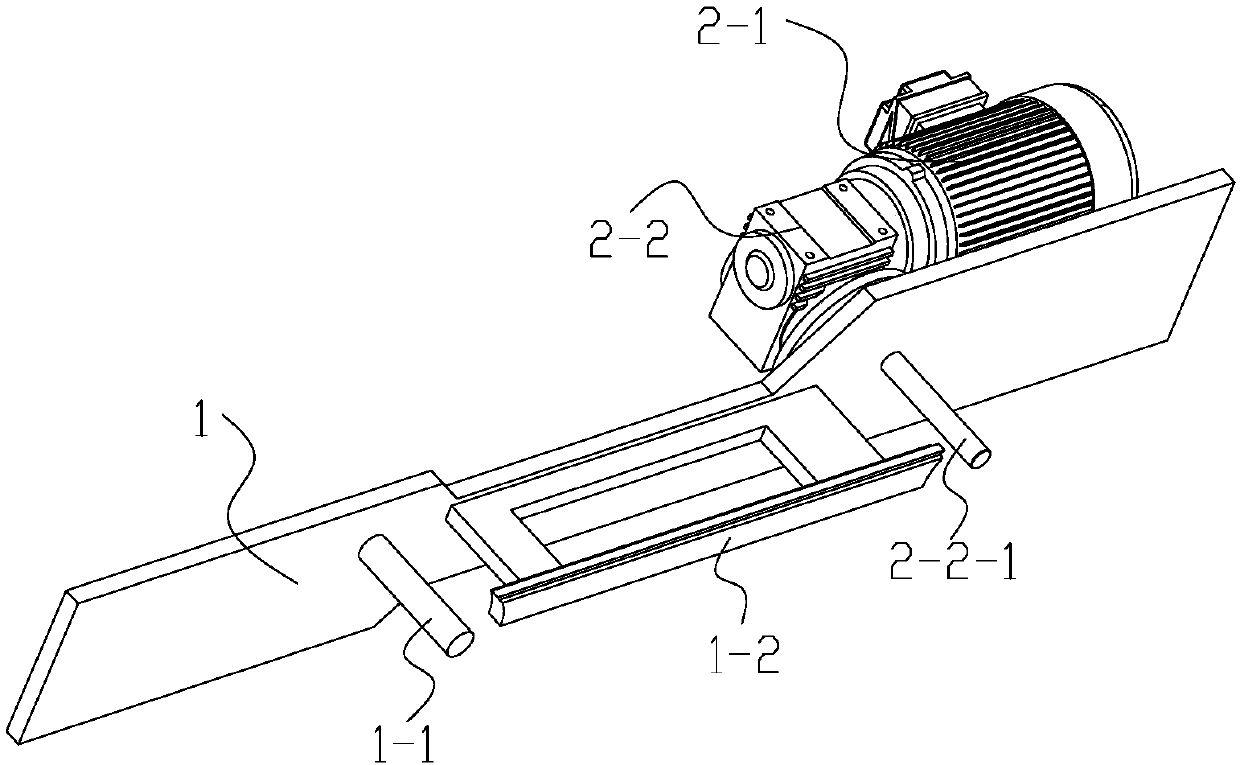
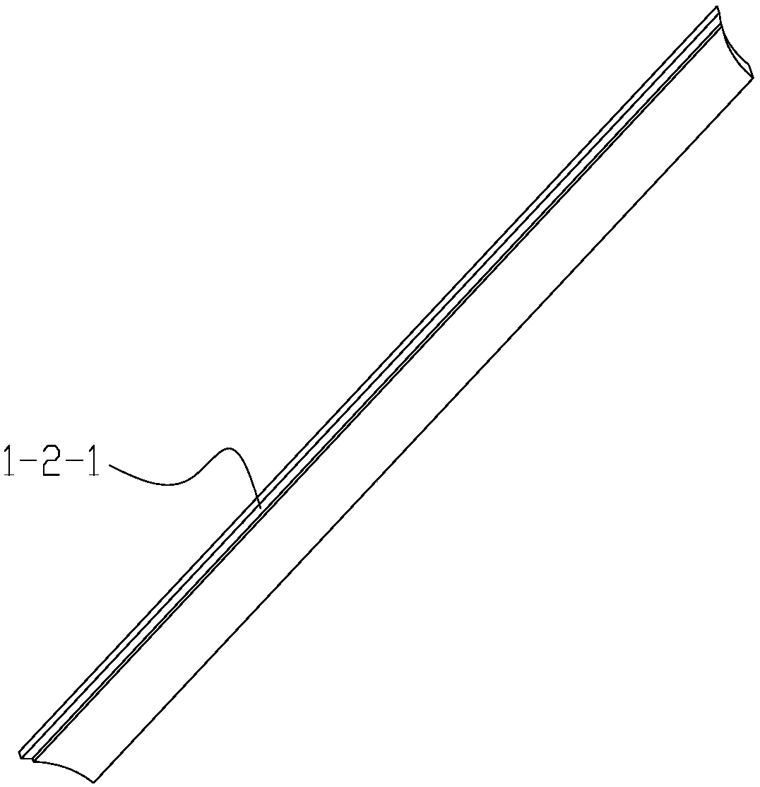
[0030] Shelf plate 1, on which a drive mechanism 2 is fixed, the first output shaft 2-2-1 of the drive mechanism 2 passes through the shelf plate 1, and one side of the shelf plate 1 is extended with an erection column 1-1, the first output The plane where the shaft 2-2-1 and the axis of the erection column 1-1 are located is horizontal, and an erection plate 1-2 is arranged between the two erection columns 1-1, and the erection plate 1-2 is fixedly connected with the erection plate 1, and the erection plate 1-2 is provided with card set convex strip 1-2-1;

[0031] Two sprockets 3, one sprocket 3 is set on the first output shaft 2-2-1, and the other sprocket 3 is rotatably set on the erection column 1-1;

[0032] Chain 4, chain 4 is set on the two sprockets 3, and the raised strip 1-2-1 is set in the chain 4; the chain 4 is provi...


PUM


Abstract

The invention provides an automatic conveying mechanism for conveying a carbon rod. The automatic conveying mechanism is characterized in that a driving mechanism is fixed on a frame plate, a first output shaft of the driving mechanism penetrates through the frame plate, erection columns extend from one side of the frame plate, the planes where the axis of the first output shaft and the axes of the erection columns are located are horizontal, an erection plate is arranged between the two erection columns, the erection plate is fixedly connected with the frame plate, and clamping convex stripsare arranged on the erection plate; and a chain wheel is arranged and is fixed to the first output shaft in a sleeving mode, another chain wheel is rotatably arranged on the erection columns in a sleeving mode, a chain is clamped on the two chain wheels, the clamping convex strips are clamped in the chain, a plurality of material taking parts are arranged on the chain, a material taking cavity isfixed on one side of the chain, the material taking parts are suitable for taking out a tubular material in the material taking cavity, a material storage cavity is fixed on the other side of the chain, and the material taking parts are suitable for placing the polished tubular material. According to the automatic conveying mechanism, the effects of automatic material taking and automatic materialplacing can be realized conveniently.

Description

technical field [0001] The invention relates to a grinder, in particular to an automatic feeding mechanism for conveying carbon rods. Background technique [0002] Polishing carbon rods in the prior art is mostly through manual clamping and grinding. The whole process takes a lot of time and cost. [0003] Therefore, it is necessary to replace the manual process if an automatic feeding mechanism can be provided. Contents of the invention [0004] The technical problem to be solved by the present invention is: in order to solve the problem in the prior art that the feeding and unloading of the grinding machine needs to be realized by manpower. The present invention provides an automatic feeding mechanism for conveying carbon rods to solve the above problems. [0005] The technical solution adopted by the present invention to solve the technical problem is: an automatic feeding mechanism for transporting carbon rods, comprising: [0006] A frame plate, a drive mechanism ...

Claims


Application Information

Patent Timeline
Patent Type & Authority Applications(China)
IPC IPC(8): B65G17/38
CPCB65G17/38
Inventor 杨文娟
Owner 江苏双辉环境科技有限公司
Why Eureka
Try Eureka