Locking mechanism and image forming apparatus
A technology for locking components and locking positions, which can be applied to devices for locking portable objects, image communication, and electrical recording technology using charge patterns, etc., and can solve problems such as increased cost and increased size of locking mechanisms
- Summary
- Abstract
- Description
- Claims
- Application Information
AI Technical Summary
Problems solved by technology
Method used
Image
Examples
no. 1 example
[0036] (Overall Structure of Image Forming Apparatus)
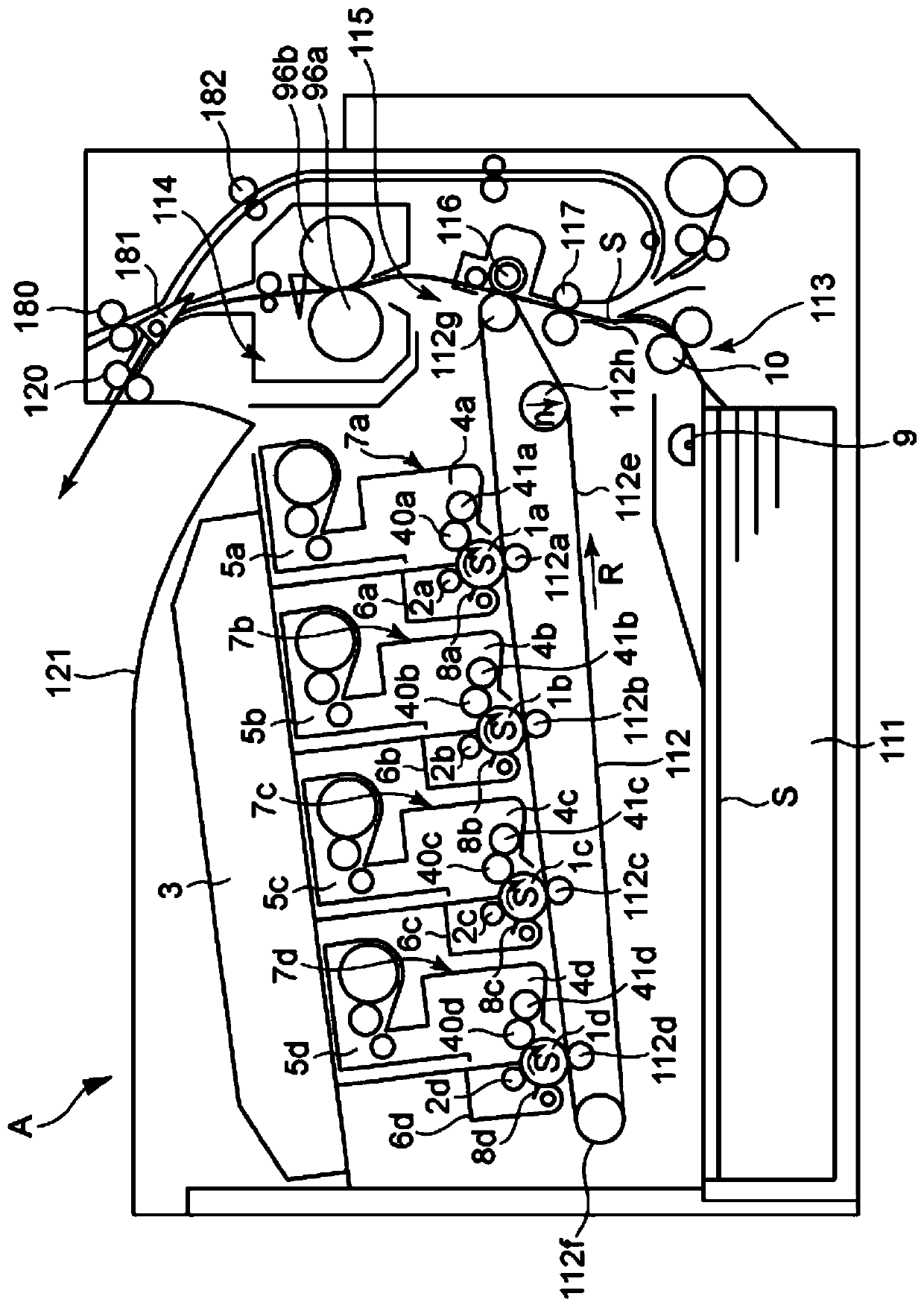
[0037] The overall configuration of the image forming apparatus will be described. The image forming apparatus is an electrophotographic color laser printer, but is not limited thereto. The image forming apparatus may be, for example, a black and white laser printer.
[0038] figure 1 The illustrated color image forming apparatus includes four process cartridges 7a, 7b, 7c, and 7d detachably attached to the main body A of the image forming apparatus. The four process cartridges 7a, 7b, 7c, and 7d have the same structure, but accommodate toners of different colors, ie, yellow (Y), magenta (M), cyan (C), and black (Bk). Therefore, the process cartridges are differentiated in that the process cartridges form images of different colors. The process cartridges 7a, 7b, 7c and 7d are constituted by developing units 4a, 4b, 4c and 4d and toner units 5a, 5b, 5c and 5d. The developing units 4a, 4b, 4c, and 4d have photosensiti...
no. 2 example
[0106] This embodiment will describe an image forming apparatus employing a shielding plate having a configuration different from that of the first embodiment in terms of shielding the magnetic field from the holding solenoid described in the first embodiment. Components constructed in the same manner as the first embodiment are attached with the same reference numerals or the same member names (even if the reference numerals are different), and descriptions thereof will be omitted.
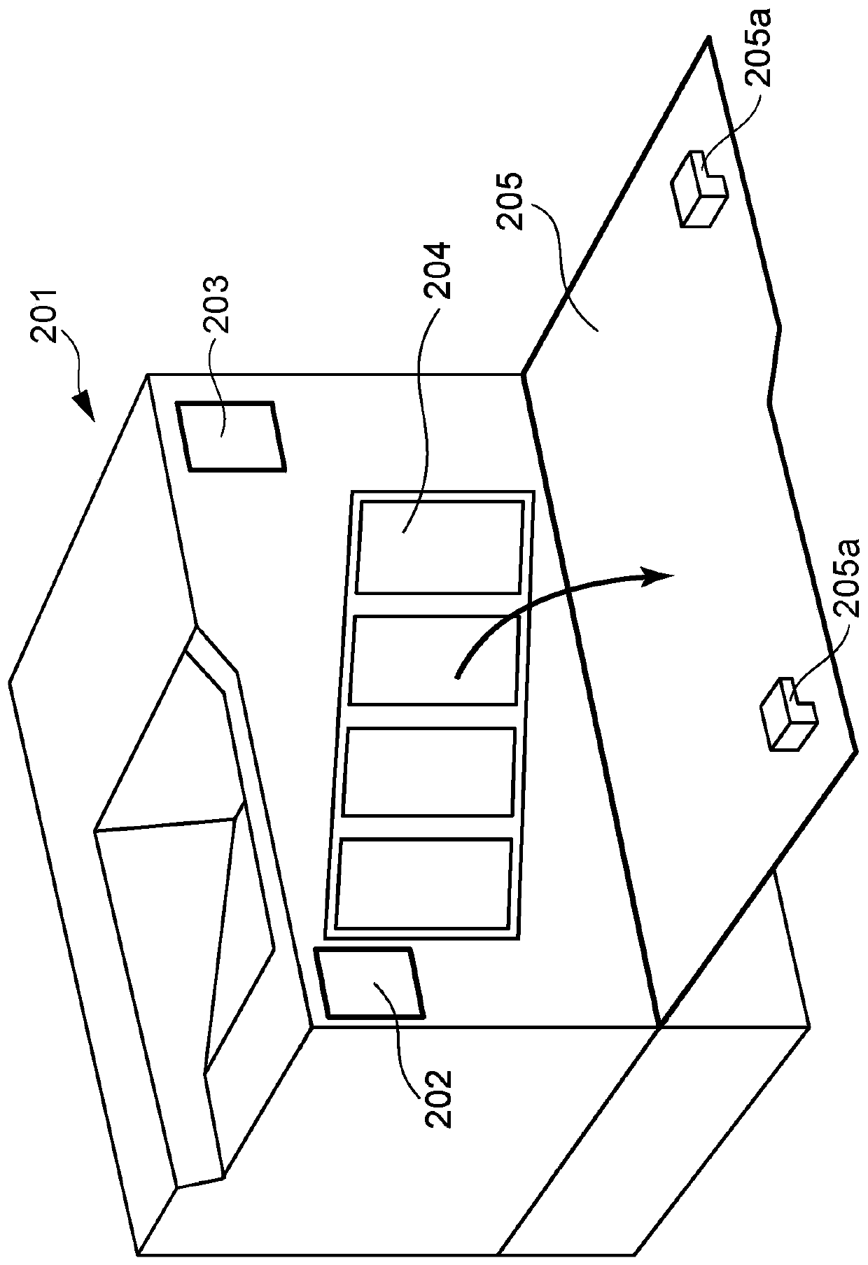
[0107] Figure 20 is a perspective view of the locking unit arranged in the device body. The locking unit is arranged in the apparatus main body frame 401 as in the first embodiment. In the present embodiment, the locking unit cover 403 covering the locking unit, which is omitted in the first embodiment, is also illustrated. Part of the locking lever 302 can be seen through the hole in the locking unit cover (although in Figure 20 , the locking lever is shown in the locked position for conven...
no. 3 example
[0114] An image forming apparatus having the locking mechanism according to the third embodiment will be described. Components constructed in the same manner as the first and second embodiments are attached with the same reference numerals or the same member names (even if the reference numerals are different), and descriptions thereof will be omitted.
[0115] (locking mechanism)
[0116] In the first and second embodiments, the configuration in which the locking unit as the locking mechanism is arranged on the front side of the frame of the main body of the image forming apparatus is described. In the present embodiment, the locking unit in the case of being arranged on the back side of the frame will be described.
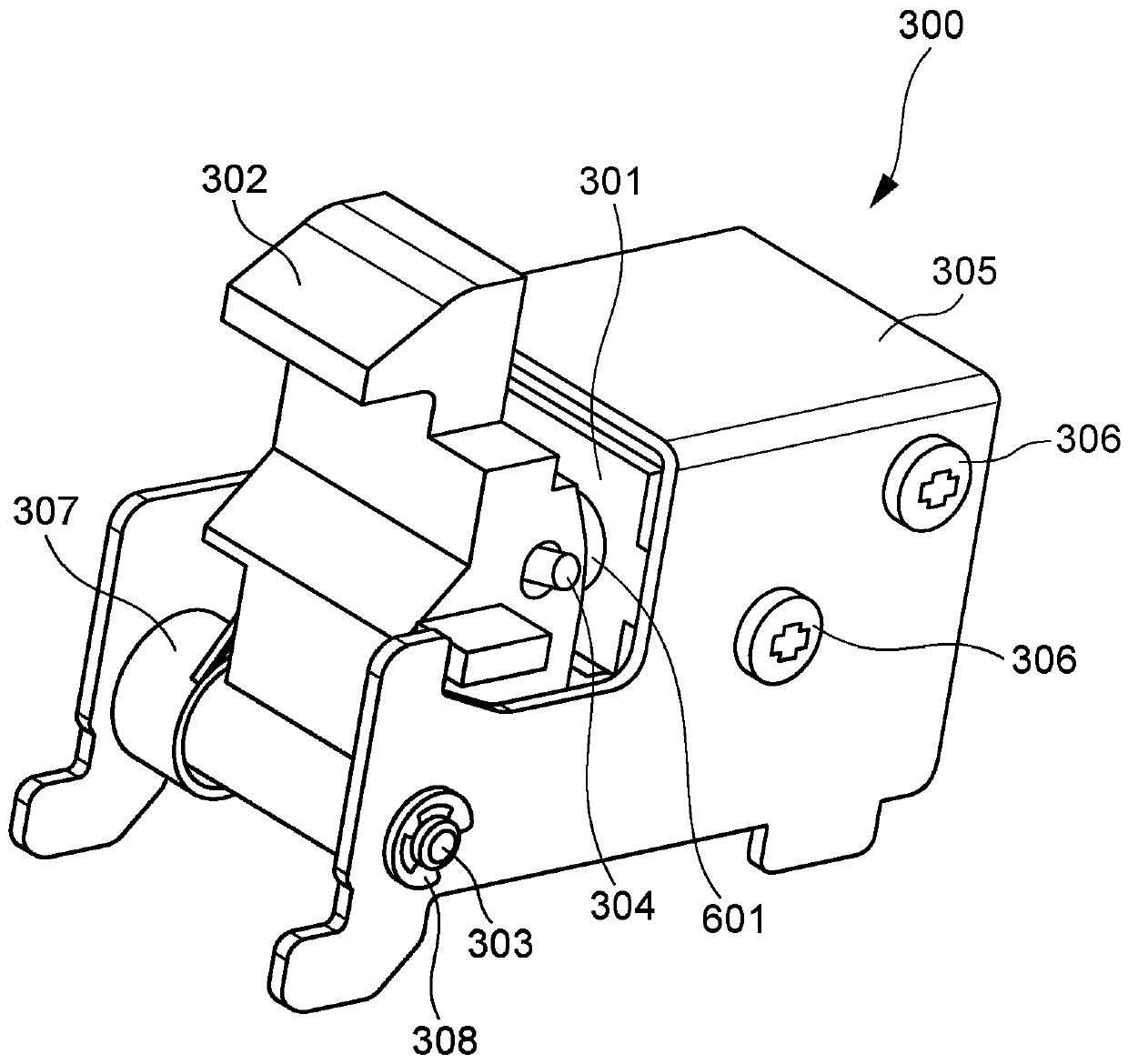
[0117] like Figure 11 As shown, the locking unit as a locking mechanism includes a holding solenoid 301 , a locking lever 501 serving as a locking member, a locking lever shaft 502 , and a pin for connecting (engaging) the locking lever 501 with the holding s...
PUM
 Abstract
Description
Claims
Application Information
 - R&D Engineer
- R&D Manager
- IP Professional
- Industry Leading Data Capabilities
- Powerful AI technology
- Patent DNA Extraction
Browse by: Latest US Patents, China's latest patents, Technical Efficacy Thesaurus, Application Domain, Technology Topic, Popular Technical Reports.
© 2024 PatSnap. All rights reserved.Legal|Privacy policy|Modern Slavery Act Transparency Statement|Sitemap|About US| Contact US: help@patsnap.com


