
Track maintenance device for road detection

A maintenance device and road detection technology, which is applied to roads, tracks, ballast layers, etc., can solve problems such as slow return speed, low work efficiency, and poor vibration reduction effect, so as to simplify manual mechanical operations and improve work efficiency , the effect of reducing the workload

Inactive Publication Date: 2019-09-06
张家港保税区康华贸易有限公司
View PDF0 Cites 2 Cited by
  • Summary
  • Abstract
  • Description
  • Claims
  • Application Information

AI Technical Summary

Problems solved by technology

[0002] With the continuous development of China's rail technology, the rails are mainly divided into high-speed rail rails, motor car rails, train rails, and subway rails. Rail maintenance is becoming more and more frequent, especially for the shock-absorbing stones on both sides of the rails. manpower to maintain it; but the existing maintenance methods for pushing the shock-absorbing stones on both sides of the rails have the following defects: because high-speed rails, bullet trains, trains, and subways will generate a lot of vibration when they move on the rails, in order to reduce the vibration Generally, a large number of stones are laid on both sides of the rails to achieve the purpose of vibration reduction. However, as time goes by, the stones on both sides of the rails will slowly slide to the sides with the vibration force, and the vibration reduction effect will become worse. Therefore, it is necessary to manually remove the stones regularly. It takes a long time to manually push the stones back together to both sides of the rails, the speed of returning is slow, the closing effect is poor, and the work efficiency is low

Method used


Image

  • Track maintenance device for road detection
  • Track maintenance device for road detection
  • Track maintenance device for road detection

Examples


Embodiment Construction

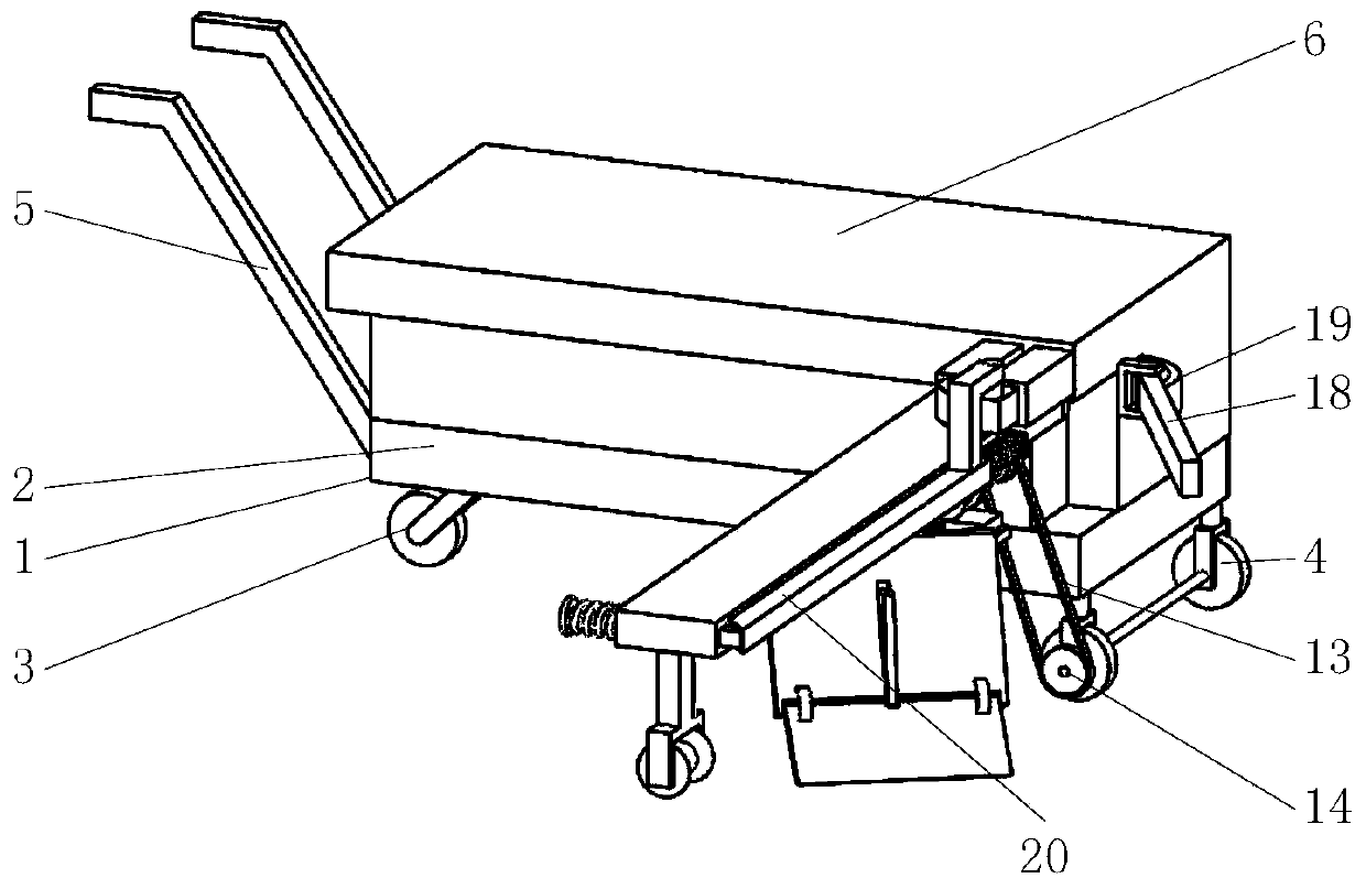
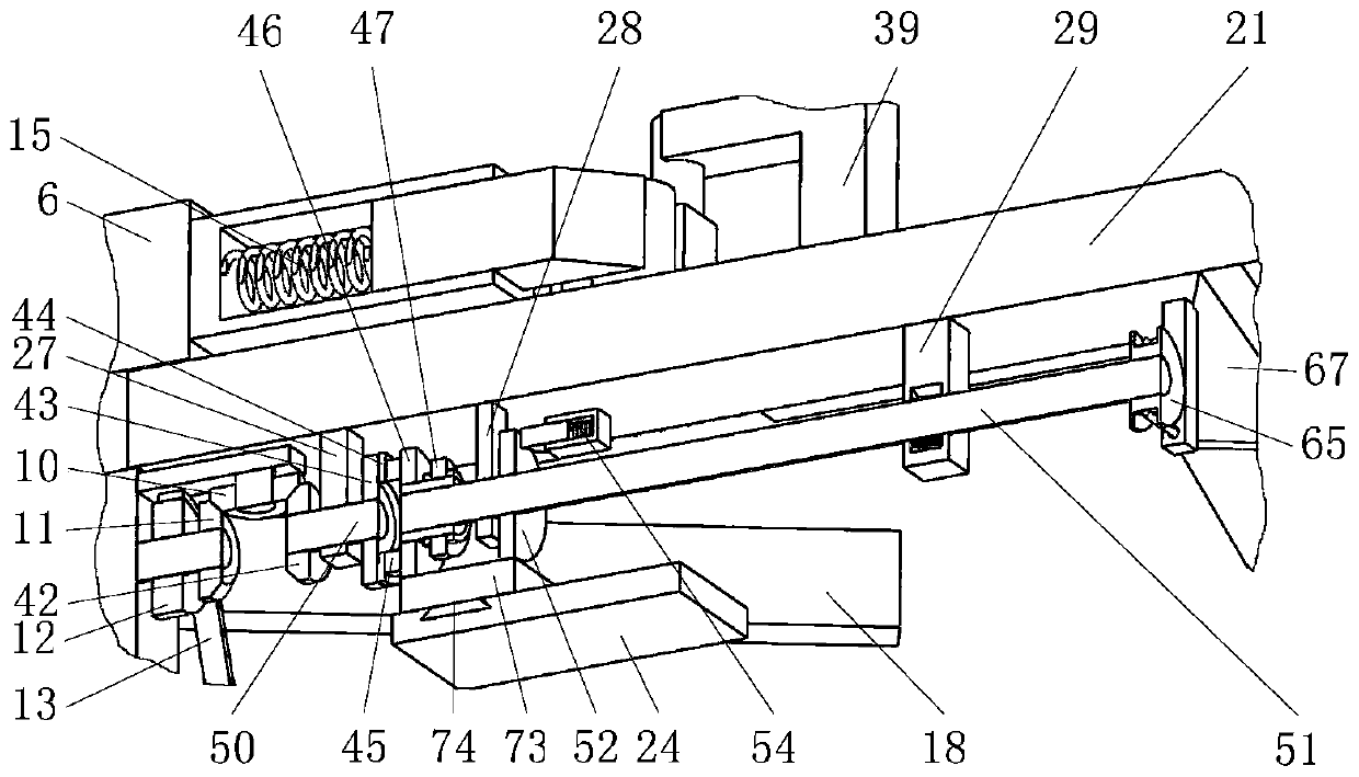
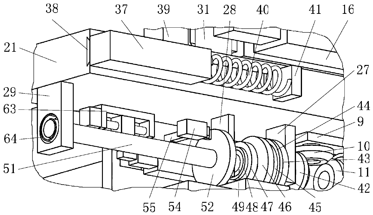
[0036] The accompanying drawings are all schematic diagrams of the implementation of the present invention, so as to understand the principle of structural operation. The specific product structure and proportional size can be determined according to the use environment and conventional technology.

[0037] Such as figure 1 , 2 As shown, it includes a diesel power module, an expansion plate A15, an expansion plate B16, and a folding mechanism 20 housed in the upper casing 6 of the car body 1, wherein as figure 1 As shown, the folding mechanism 20 is hinged to the side front end of the housing 6 and swings horizontally around its hinge point; Figure 4 , 15 As shown, the telescopic plate A15 and the telescopic plate B16 with inclined planes at the end of the inner plate are distributed horizontally at the front end of the side of the housing 6, and the telescopic plate B16 is located in front of the telescopic plate A15; figure 2 , 4 As shown, the inner plate of the teles...


PUM


Abstract

The invention belongs to the field of track detection, and particularly relates to a track maintenance device for road detection. The track maintenance device includes a car body, a shell body, an expansion plate A, an expansion plate B and a collecting mechanism, wherein the car body is provided with the shell body which provides power for the car body, and the collecting mechanism is hinged to the front end of the side of the shell body and oscillates horizontally around a hinge point; driven by the shell body, the collecting mechanism can reverse falling gravel on both sides of a track to ensure the effective shock absorption of the gravel to the track; and compared with a traditional method of manually collecting the falling gravel regularly, according to the track maintenance device for the road detection, the workload of workers is reduced, working efficiency is improved and the effect of collecting gravel is good.

Description

technical field [0001] The invention belongs to the field of rail detection, in particular to a rail maintenance device for road detection. Background technique [0002] With the continuous development of China's rail technology, the rails are mainly divided into high-speed rail rails, motor car rails, train rails, and subway rails. Rail maintenance is becoming more and more frequent, especially for the shock-absorbing stones on both sides of the rails. manpower to maintain it; but the existing maintenance method of pushing the shock-absorbing stones on both sides of the rails has the following defects: because high-speed rail, bullet trains, trains, and subways will generate a large vibration force when they move on the rails, in order to reduce the vibration Generally, a large number of stones are laid on both sides of the rails to achieve the purpose of vibration reduction. However, as time goes by, the stones on both sides of the rails will slowly slide to the sides with...

Claims


Application Information

Patent Timeline
Patent Type & Authority Applications(China)
IPC IPC(8): B61D15/00B61D15/06E01B27/02
CPCB61D15/00B61D15/06E01B27/026
Inventor 陈建方吴建康
Owner 张家港保税区康华贸易有限公司
Learn More