Antenna unit and terminal equipment

A technology of antenna unit and terminal equipment, which is applied in the direction of antenna, resonant antenna, antenna coupling, etc., and can solve the problems of few frequency bands covered by millimeter-wave antennas and poor performance of terminal equipment antennas.

Active Publication Date: 2019-09-06
VIVO MOBILE COMM CO LTD
View PDF8 Cites 11 Cited by
  • Summary
  • Abstract
  • Description
  • Claims
  • Application Information

AI Technical Summary

Problems solved by technology

[0005] An embodiment of the present invention provides an antenna unit and a terminal device to solve the problem that the existing mi...

Method used


Image

  • Antenna unit and terminal equipment
  • Antenna unit and terminal equipment
  • Antenna unit and terminal equipment

Examples


Embodiment Construction

[0025] The following will clearly and completely describe the technical solutions in the embodiments of the present invention with reference to the accompanying drawings in the embodiments of the present invention. Obviously, the described embodiments are some of the embodiments of the present invention, but not all of them. Based on the embodiments of the present invention, all other embodiments obtained by persons of ordinary skill in the art without creative efforts fall within the protection scope of the present invention.

[0026] The term "and / or" in this article is an association relationship describing associated objects, which means that there can be three relationships, for example, A and / or B can mean: A exists alone, A and B exist simultaneously, and B exists alone These three situations. The symbol " / " in this document indicates that the associated object is an or relationship, for example, A / B indicates A or B.

[0027] The terms "first" and "second" in the spec...


PUM


Abstract

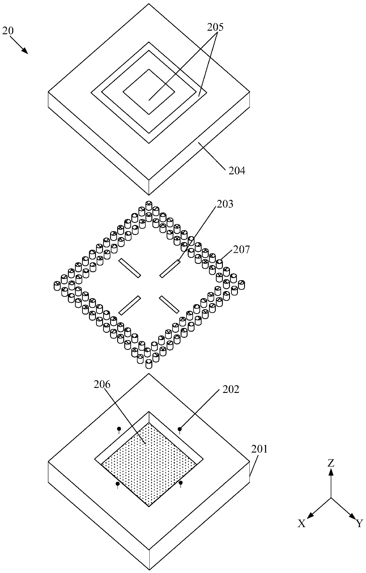
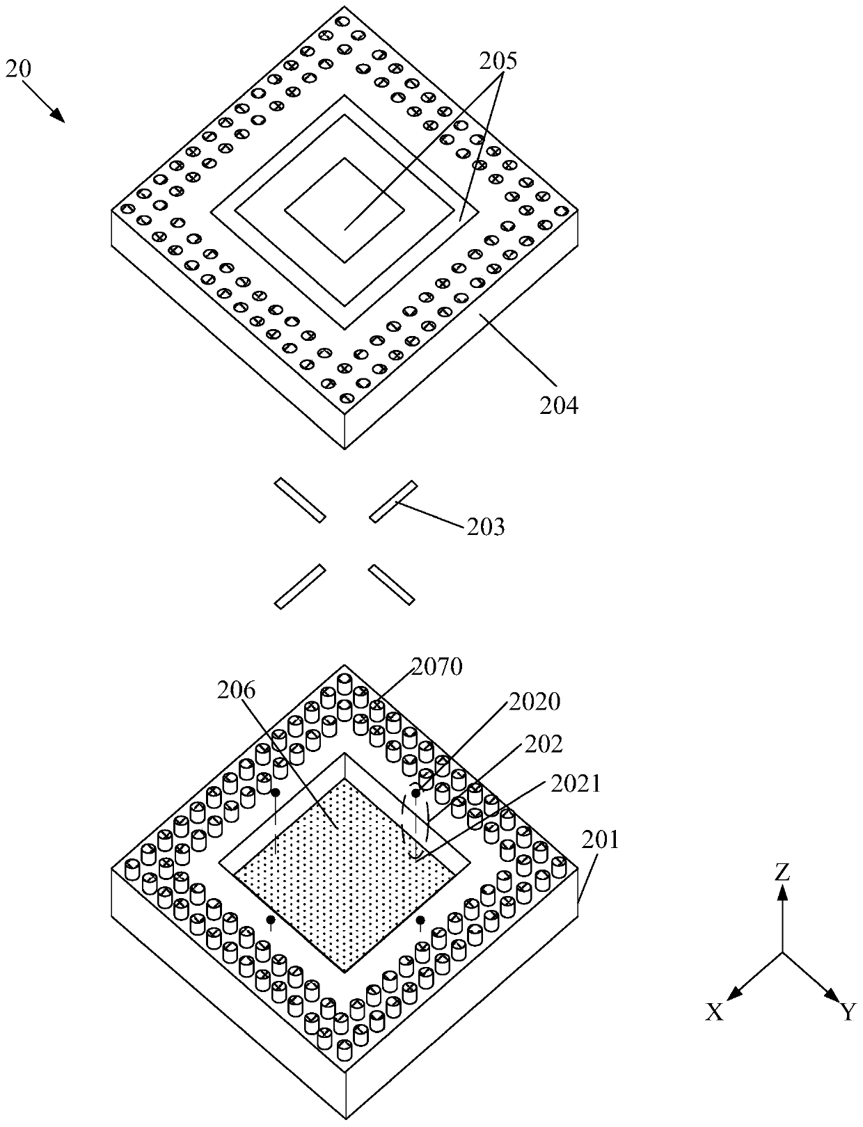
The embodiment of the invention provides an antenna unit and terminal equipment, and relates to the technical field of communication. By the antenna unit and the terminal equipment, the problem that afew frequency bands are covered by a millimeter wave antenna of the terminal equipment to cause relatively poor antenna performance of the terminal equipment is solved. The antenna unit comprises aninsulation groove, M feeding parts, M coupling bodies, a first insulator, at least two radiation bodies, a first radiation body and an isolation body, wherein the M feeding parts are arranged in the insulation groove, the at least two radiation bodies are borne by the first insulation body, the first radiation body is arranged at the bottom of the insulation groove, the isolation body is arrangedin a way encircling the M coupling bodies, the M feeding parts are isolated from the first radiation body and the isolation body, the M coupling bodies are arranged between the first radiation body and the first insulation body, each feeding part in the M feeding parts is electrically connected with one of the coupling bodies, each coupling body in the M coupling bodies is coupled to the at leasttwo radiation bodies and the first radiation body, the resonant frequencies of the different radiation bodies are different, and M is a positive integer. The antenna unit is applied to the terminal equipment.

Description

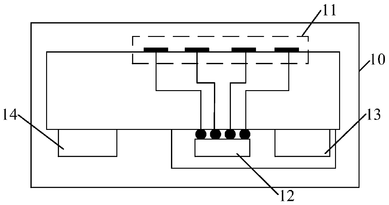
technical field [0001] Embodiments of the present invention relate to the field of communication technologies, and in particular, to an antenna unit and a terminal device. Background technique [0002] With the development of the fifth-generation mobile communication (5-generation, 5G) system and the wide application of terminal equipment, millimeter-wave antennas are gradually applied in various terminal equipment to meet the increasing usage needs of users. [0003] At present, the millimeter wave antenna in the terminal device is mainly implemented through an antenna in package (antenna in package, AIP) technology. For example, if figure 1 As shown, an array antenna 11 whose working wavelength is a millimeter wave, a radio frequency integrated circuit (radiao frequency intergarted circuit, RFIC) 12, a power management integrated circuit (power management intergarted circuit, PMIC) 13, and a connector 14 can be packaged into a A module 10 may be called a millimeter wave ...

Claims


Application Information

Patent Timeline
IPC IPC(8): H01Q1/50H01Q1/36H01Q1/52H01Q5/307H01Q5/50
CPCH01Q1/50H01Q1/36H01Q1/521H01Q5/307H01Q5/50H01Q9/0457H01Q1/243H01Q21/08H01Q19/10H01Q5/40H01Q9/045
Inventor 简宪静黄奂衢王义金马荣杰
Owner VIVO MOBILE COMM CO LTD
Why Eureka
Try Eureka