Civil engineering sand sieving device

A technology of civil engineering and sand screening, which is applied in the direction of filter screen, solid separation, grille, etc., can solve the problems of reducing the life of the screen, difficult to grasp the installation accuracy, and destroying the screen, so as to improve the screening efficiency and quality, and the structure is ingenious , to avoid the effect of replacement

Active Publication Date: 2019-09-10
ZHENGZHOU INST OF TECH
View PDF7 Cites 23 Cited by
  • Summary
  • Abstract
  • Description
  • Claims
  • Application Information

AI Technical Summary

Problems solved by technology

[0003] During the routine operation of civil engineering, it is often necessary to use sand with a qualified particle size, so as to meet the needs of the construction project. The existing sand screening device on the construction site can only screen out one kind of sand, but often due to the required sand particle size The difference between the screens makes the staff have to replace the screen, which is complicated to operate, and the screening of sand is uneven, resulting in low work efficiency; and in the construction of dams in civil engineering, rock crushing is often used to obtain sand and gravel with different particle sizes. At this time, it is also necessary to replace the screen for screening sand and gravel. It is time-consuming and laborious to replace the screen, and the installation accuracy is difficult to grasp. At the same time, when the screen is blocked or stuck, not only for the The efficiency and quality of screening will be affected, and at the same time, the screen will be damaged to a certain extent, and the life of the screen will be reduced. Therefore, we urgently need a sand screening device for civil engineering to solve the above problems.

Method used


Image

  • Civil engineering sand sieving device
  • Civil engineering sand sieving device
  • Civil engineering sand sieving device

Examples


Embodiment 1

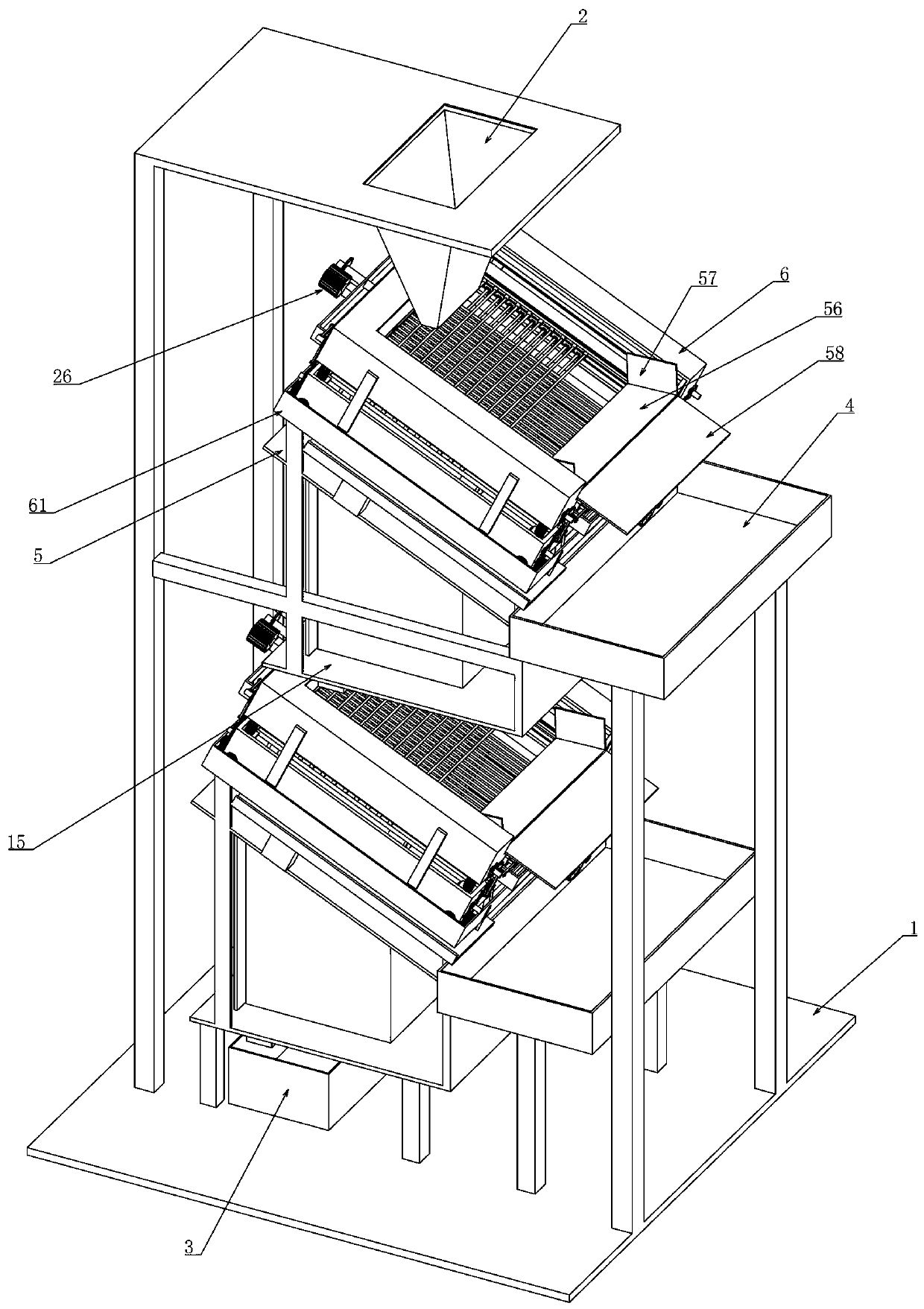
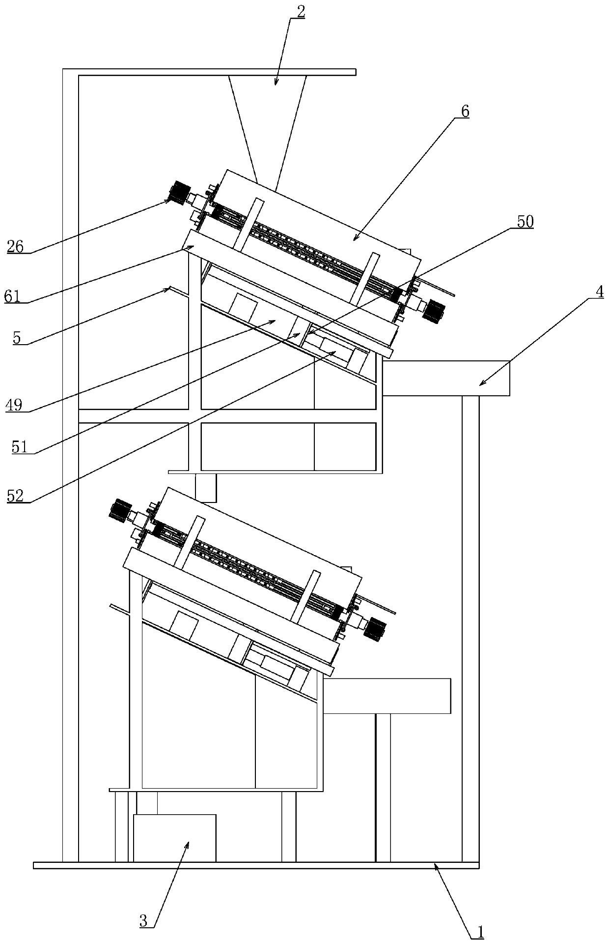
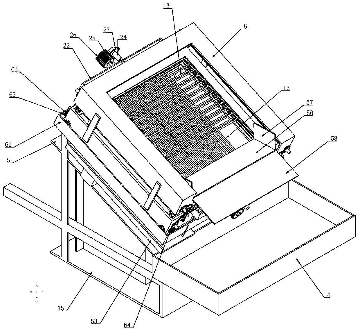
[0035] Embodiment one, combined with the attached Figure 1-17 , a civil engineering sand screening device, including a bracket 1, the bracket 1 can be fixed and installed in the area where it needs to be applied through anchor bolts, and it is characterized in that the upper end of the bracket 1 is connected from top to bottom with multiple groups of vertically arranged Sand screening device, the discharge end of the upper sand screening device is connected to the feed end of the lower sand screening device, the sand screened by each layer of sand screening device enters the sand screening device below, and the sand screening device on the uppermost layer The upper end of the device is connected to a raw material storage box 2, and the discharge end of the raw material storage box 2 is connected to the feeding end of the uppermost sand screening device. The raw material storage box 2 can be used to hold sand or gravel to be screened , the discharge end of the sand screening d...

Embodiment 2

[0038] Embodiment two, on the basis of embodiment one, in conjunction with the attached Figure 1-17 , the two ends of the transverse bar 12 are connected with a fixed block 17, the fixed block 17 is longitudinally slid between the two square frames 11, and a limit device is set so that it can only be carried out along the longitudinal direction of the square frame 11. To move, the ends of the fixed blocks 17 are respectively provided with front and rear symmetrical slopes, and the longitudinal spacing adjustment device includes a triangular wedge that is vertically limited by the square frame 11 and is horizontally slidable between two adjacent groups of fixed blocks 17. 18. The triangular wedge 18 cooperates with the side wall and the inclined surface of the fixed block 17. With the movement of the triangular wedge 18, the distance between adjacent fixed blocks 17 is adjusted. At the same time, due to the existence of the inclined surface, the triangular wedge 18 does not As...

Embodiment 3

[0040] Embodiment three, on the basis of embodiment one, in conjunction with the attached Figure 1-17 , the two ends of the transverse bar 12 are respectively connected with a second slider 32, and the second slider 32 is horizontally slidably fitted between the square frame 11 and the rectangular frame 7, and the upper end of the second slider 32 is connected to the section It is a T-shaped slide block, and there is a T-shaped chute matching it on the rectangular frame 7, so that the second slide block 32 can only move along the lateral direction of the rectangular frame 7. The lateral spacing adjustment device It includes a plurality of sets of through holes 33 provided by the second slider 32, one side of the through holes 33 is rotatably connected to a second lead screw 34 which is hollow inside, and the other side of the through holes 33 is coaxially connected to a set of The sleeve 35, the sleeve 35 is provided with an internal thread that is threadedly matched with the...


PUM


Abstract

The invention relates to a civil engineering sand sieving device. The civil engineering sand sieving device uses crosses formed by transverse rods and longitudinal rods for forming a sieving net structure, enables the transverse rods and the longitudinal rods to perform equal interval adjustment according to requirements through a transverse interval adjustment device and a longitudinal interval adjustment device, and simultaneously uses a locking function of a hydraulic telescopic rod in a hydraulic cylinder and a self-locking function of threads for achieving position locking after the equalinterval adjustment, enables the transverse rods and the longitudinal rods in the sieving net structure to be stable and reliable in the sieving process, is suitable for different grain diameters offine sand or sand stone, and avoids replacement of a sieving net, and meanwhile a power device drives the transverse rods and the longitudinal rods, which cooperate with one another, to separate whenhole blocking of the sieving net occurs or the sieving net needs to be cleaned, and then achieves cleaning effect by adjusting intervals. The civil engineering sand sieving device is simple to operateand ingenious in structure, avoids the replacement of the sieving net, and meanwhile can clean up the sieving net timely, and greatly improves sieving efficiency and quality.

Description

technical field [0001] The invention belongs to the technical field of sand screening devices, in particular to a sand screening device for civil engineering. Background technique [0002] Civil engineering refers to the general term for the science and technology of constructing various land engineering facilities. Civil engineering refers to various technical work such as survey, planning, design, construction, installation and maintenance for new construction, reconstruction or expansion of buildings, structures and related supporting facilities, etc. engineering entities. [0003] During the routine operation of civil engineering, it is often necessary to use sand with a qualified particle size, so as to meet the needs of the construction project. The existing sand screening device on the construction site can only screen out one kind of sand, but often due to the required sand particle size The difference between the screens makes the staff have to replace the screen,...

Claims


Application Information

Patent Timeline
Patent Type & Authority Applications(China)
IPC IPC(8): B07B1/28B07B1/42B07B1/46B07B1/50
CPCB07B1/28B07B1/42B07B1/4636B07B1/50B07B2201/04
Inventor 王丽霖刘喜王倩倩
Owner ZHENGZHOU INST OF TECH
Why Eureka
Try Eureka