Driving mode switching system, method and device for automatic driving, and storage medium

A technology of automatic driving and driving mode, applied in the direction of electric steering mechanism, power steering mechanism, external condition input parameters, etc., which can solve the problem of depriving users of self-rescue ability, not satisfying self-driving vehicles, and difficult to coordinate motor assistance and users hand torque etc.

Active Publication Date: 2019-09-10
AIWAYS AUTOMOBILE CO LTD
View PDF5 Cites 14 Cited by
  • Summary
  • Abstract
  • Description
  • Claims
  • Application Information

AI Technical Summary

Problems solved by technology

The traditional EPS steering system will not be able to meet the use of self-driving vehicles well in terms of structure, because the EPS steering wheel of the transmission is mechanically connected with the steering rack through mechanical results.
Any input from the user will be reflected on the rack. Therefore, it is difficult to coordinate the motor power and the user's hand torque, especially for L4-level self-driving cars. Self-driving cars cannot be interfered by humans at all, and when the judgment of automatic driving is wrong , the people in the car have no way to save themselves
[0004] This creates a dilemma in current steer-by-wire systems. If the steering wheel and steering rack are mechanically connected, user input can easily interfere with motor assist.
If the two are completely separated, the user will completely lose the sense of precise control of the manual and intuitive driving of the car, and when turning, the user will feel great panic when looking at the motionless steering wheel, and when encountering a dangerous situation, automatically When the driving judgment is wrong, it completely deprives the user of the ability to save himself

Method used


Image

  • Driving mode switching system, method and device for automatic driving, and storage medium
  • Driving mode switching system, method and device for automatic driving, and storage medium
  • Driving mode switching system, method and device for automatic driving, and storage medium

Examples


Embodiment Construction

[0066] Example embodiments will now be described more fully with reference to the accompanying drawings. Example embodiments may, however, be embodied in many forms and should not be construed as limited to the embodiments set forth herein. Rather, these embodiments are provided so that this disclosure will be thorough and complete, and will fully convey the concept of the example embodiments to those skilled in the art. The same reference numerals denote the same or similar structures in the drawings, and thus their repeated descriptions will be omitted.

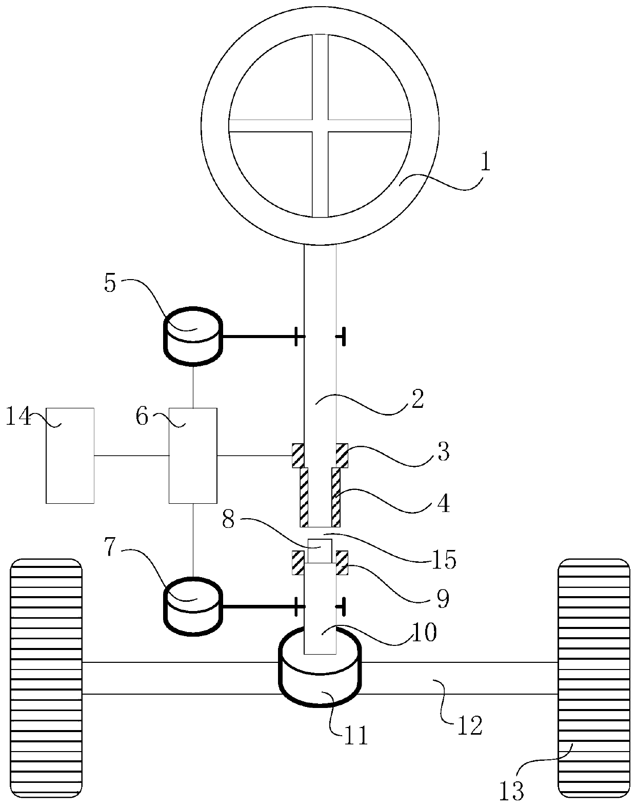
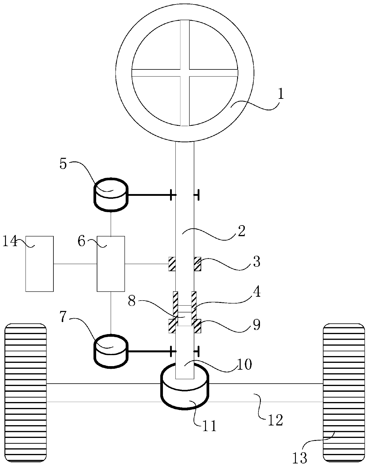
[0067] figure 1 is a schematic diagram of the driving mode switching system for automatic driving of the present invention in the first state. figure 2 is a schematic diagram of the driving mode switching system for automatic driving of the present invention in the second state. Such as figure 1 and 2 As shown, the driving mode switching system for automatic driving of the present invention includes: a steering wheel ...


PUM


Abstract

The invention provides a driving mode switching system, method and device for automatic driving and a storage medium. The system comprises the following parts: a steering wheel; a steering input shaftwith a first end connected with the steering wheel; a connecting sleeve with a first end connected with a second end of the steering input shaft in a sleeving manner; a steering output shaft that iscoaxially arranged with the steering input shaft, and a gap is formed between a first end of the steering output shaft and the second end of the steering input shaft; and a control assembly that enables the connecting sleeve to run in the axial direction of the steering input shaft, so that the connecting sleeve has a first state of being limited to the steering input shaft and a second state of being connected with the steering input shaft and the steering output shaft and coaxially transmitting a rotating force. According to the method and device and system, free switching between two different driving modes can be realized, the driving pleasure is enhanced, the humanized experience of driving an automatic driving automobile is improved, and the popularization and promotion of the automatic driving automobile are facilitated.

Description

technical field [0001] The invention relates to the field of automatic driving of automobiles, in particular to a driving mode switching system, method, device and storage medium for automatic driving. Background technique [0002] Self-driving cars, which can safely take passengers from one destination to another within the applicable area, are increasingly becoming a research hotspot. As the brain of autonomous driving, the automatic driving controller realizes the fusion and processing of environmental perception information, and decides the driving behavior of the vehicle to safely drive to the destination. [0003] EPS is the abbreviation of Electrical Power Steering in English, which means "electronic power steering system". The EPS system is generally composed of a mechanical steering system plus a torque sensor, a vehicle speed sensor, an electronic control unit, a reducer, and an electric motor. , using the electronic control device to make the motor generate auxi...

Claims


Application Information

Patent Timeline
Patent Type & Authority Applications(China)
IPC IPC(8): B60W30/182B60W10/20B62D5/04
CPCB60W10/20B60W30/182B60W2710/20B62D5/0409B62D5/043B60W2554/80B60W2554/801
Inventor 王志忠
Owner AIWAYS AUTOMOBILE CO LTD
Why Eureka
Try Eureka