Parallel groove wire clamp

A wire clip and clip body technology, applied in the direction of electrical components, circuits, connections, etc., can solve the problems of not being able to effectively adapt to different specifications of twisted wires, unstable clamping, etc., and achieve easy disassembly, easy protection, and strong adaptability Effect

Inactive Publication Date: 2019-09-10
YANTAI POWER SUPPLY COMPANY OF STATE GRID SHANDONG ELECTRIC POWER +1
View PDF4 Cites 8 Cited by
  • Summary
  • Abstract
  • Description
  • Claims
  • Application Information

AI Technical Summary

Problems solved by technology

[0004] The purpose of the present invention is to solve the problem of unstable clamping due to the fixed size of most parallel g

Method used


Image

  • Parallel groove wire clamp
  • Parallel groove wire clamp
  • Parallel groove wire clamp

Examples


Embodiment 1

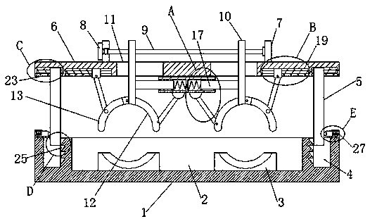
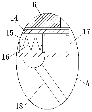
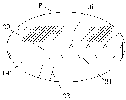
[0026] refer to Figure 1-6 , a parallel groove clamp, including a fixed seat 1, the top of the fixed seat 1 is provided with a connecting groove 2, the bottom inner wall of the connecting groove 2 is provided with two lower clip bodies 3, and the top of the fixed seat 1 is provided with two sockets Slot 4, two insertion rods 5 are movably installed in the two slots 4, and the tops of the two insertion rods 5 are slidingly connected with the same pressure plate 6, and the top of the pressure plate 6 is fixedly installed with two bearing seats 7, two bearings The same threaded rod 9 is rotatably installed on the seat 7, and a rotating block 8 is installed on the side of one bearing seat 7 of the two bearing seats 7 away from the other bearing seat 7, and one end of the threaded rod 9 is fixedly installed on the rotating block 8 On, two transmission shafts 10 are threadedly connected on the threaded rod 9, and two transmission shafts 10 are provided with threaded holes, and the ...

Embodiment 2

[0035] refer to Figure 1-6 , a parallel groove clamp, including a fixed seat 1, the top of the fixed seat 1 is provided with a connecting groove 2, the bottom inner wall of the connecting groove 2 is provided with two lower clip bodies 3, and the top of the fixed seat 1 is provided with two sockets Slot 4, two insertion rods 5 are movably installed in the two slots 4, and the tops of the two insertion rods 5 are all slidably connected with the same pressure plate 6, and the top of the pressure plate 6 is fixedly installed with two bearing seats 7 by welding. The same threaded rod 9 is rotatably installed on the two bearing seats 7, and a rotating block 8 is installed on the side of one bearing seat 7 away from the other bearing seat 7 in the two bearing seats 7, and one end of the threaded rod 9 is fixedly installed by welding. On the rotating block 8, two transmission shafts 10 are threadedly connected on the threaded rod 9, and threaded holes are provided on the two transmi...


PUM


Abstract

The invention belongs to the technical field of wire clamps, particularly relates to a parallel groove wire clamp, and aiming at solving the problem that clamping is unstable due to the fact that thedimensions of the majority of the existing parallel groove wire clamps are fixed and cannot be adapted to stranded wires of different specifications. A scheme is proposed as follows: the parallel groove wire clamp comprises a fixed base, wherein a connecting groove is formed in the top of the fixed base; two lower clamping bodies are arranged on the inner wall of the bottom of the connecting groove; two inserting grooves are formed in the top of the fixed base; two inserting rods are movably installed in the two inserting grooves; the top ends of the two inserting rods are connected with the same pressing plate in a sliding mode; two bearing pedestals are fixedly arranged at the top of the pressing plate; and the two bearing pedestals are rotationally provided with the same threaded rod. The parallel groove wire clamp can be well adapted to the stranded wires of different specifications for use, so that strong adaptability is achieved, the extrusion and buffering can be carried out onthe extrusion firstly, and the stranded wires can be protected conveniently; and meanwhile, disassembly is convenient, so that the development of overhaul and maintenance is facilitated.

Description

technical field [0001] The invention relates to the technical field of wire clamps, in particular to a parallel groove wire clamp. Background technique [0002] The parallel trench clamp is used for the connection of small and medium-sized aluminum stranded wires or steel-cored aluminum stranded wires and the steel stranded wires of overhead lightning conductors at positions that do not bear tension, and is also used for jumper connections of non-linear pole towers. Power engineering materials (fittings) are used to connect wires to each other and are mainly used in power line engineering. Ditching clamps are used to connect two parallel wires to transmit electrical loads. Contact fittings are widely used, such as jumpers for non-linear poles and towers. 1. T-connection, branch line, switch, transformer and other electrical equipment down-leads at the non-load-bearing connection of the power system, grounding down-leads of lightning conductors, etc. can be completed by using...

Claims


Application Information

Patent Timeline
IPC IPC(8): H01R11/01
CPCH01R11/01
Inventor 李刚王珏柳建伟
Owner YANTAI POWER SUPPLY COMPANY OF STATE GRID SHANDONG ELECTRIC POWER
Why Eureka
Try Eureka