Finger fracture fixation rack

A fixing frame and finger technology, applied in fractures, medical science and other directions, can solve the problems of poor fixation effect and poor fixation effect of finger fractures, and achieve the effects of firm fixation, simple use method and infection prevention.

Inactive Publication Date: 2019-09-13
漯河市第一人民医院
View PDF7 Cites 0 Cited by
  • Summary
  • Abstract
  • Description
  • Claims
  • Application Information

AI Technical Summary

Problems solved by technology

However, this patent only relies on the airbag to fix the palm, without external support...

Method used


Image

  • Finger fracture fixation rack
  • Finger fracture fixation rack
  • Finger fracture fixation rack

Examples


Embodiment 1

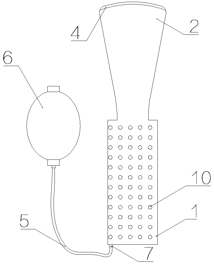
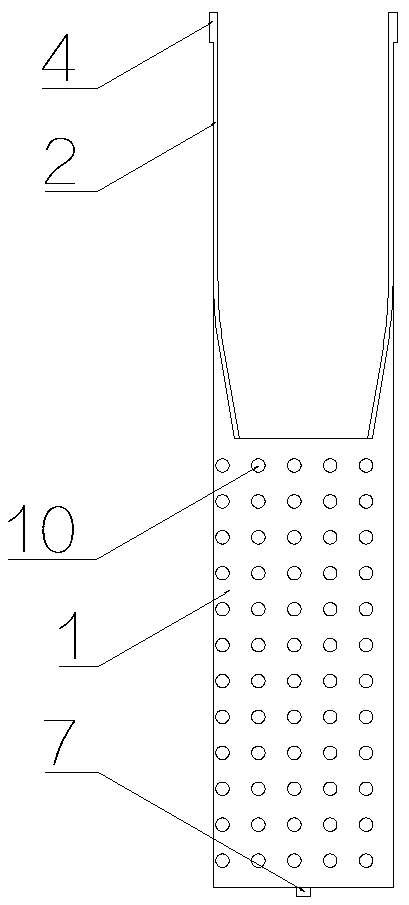
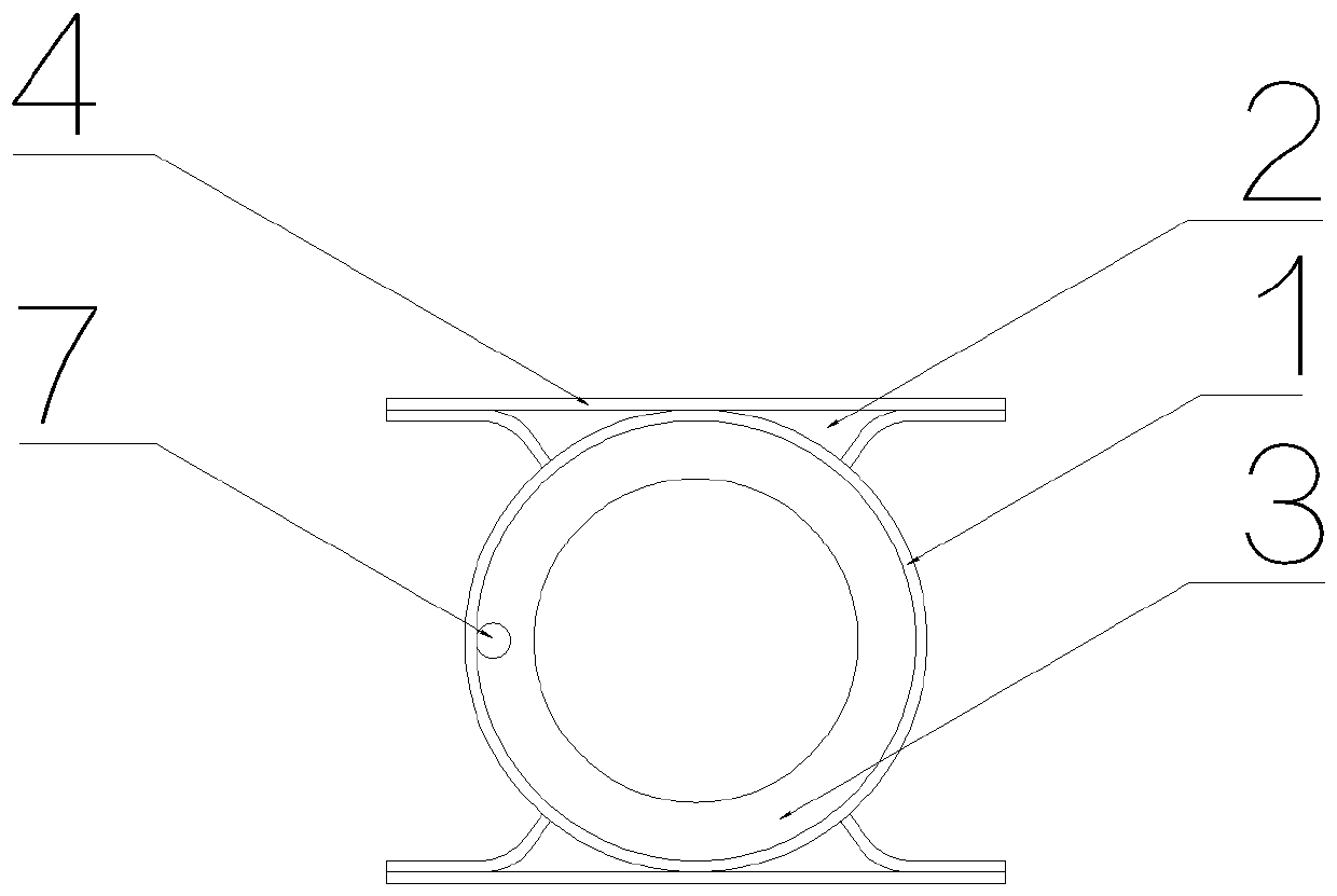
[0036] Such as Figure 1-3 As shown, a finger fracture fixation frame includes a protective shell 1, a support plate 2, and an inflatable cushion 3. The protective shell 1 is a cylindrical hard shell, and the protective shell 1 is provided with a ventilation hole 10. The air holes 10 are evenly distributed on the shell of the protective shell 1, the diameter of the protective shell 1 is 3 cm, the wall thickness is 1 mm, and the diameter of the vent hole 10 is 3 mm, so as to ensure the ventilation and dryness of the bandaged wound Comfortable and avoid infection from happening.

[0037] The support plate 2 is a hard plate, which is fixedly connected to one end of the protective shell 1, and the end of the support plate 2 is provided with a position-limiting protrusion 4, and the height of the position-limiting protrusion 4 is 1 mm. It is integrally formed with the protective shell 1, and the support plate 2 is symmetrically arranged on both sides of the upper port of the prote...

Embodiment 2

[0041] Such as Figure 4 As shown, the structure of this embodiment is basically the same as that of Embodiment 1, the difference being that: the strap 13 and the fixing strap 11 are set on the support plate 2, and two straps 13 are arranged side by side on each support plate, so The loop belt 13 and the support plate 2 are integrally formed, the fixing belt 11 is an elastic belt, and the two ends of the fixing belt 11 are respectively provided with a child sticker 12a and a female sticker 12b of the Velcro one. During use, the fixing belt 11 passes through the loop 13, and the sub-stick 12a and the mother stick 12b of the Velcro 1 cooperate with each other to fix the support plate 2 on the palm or the wrist. There is no need for professional doctors to operate, no need to use medical tape, fast and convenient fixation and removal.

Embodiment 3

[0043] Such as Figure 5As shown, the structures of the present embodiment and the second embodiment are basically the same, the difference is that the protective shell 1 and the support plate 2 are separate structures, the lower end of the support plate 2 is extended to form an extension arm 15, and the extension arm 15 is in the shape of an arc plate, and the end of the extension arm 15 is provided with a hook 16 . When in use, the extension arm 15 of the support plate 2 is inserted into the inside of the protection case 1, and the hook 16 is hooked to the lower end of the protection case 1, and the extension arm 15 is located between the protection case 1 and the protection case 1. Between 3 inflatable cushions.


PUM


Abstract

The invention discloses a finger fracture fixation rack. The finger fracture fixation rack comprises a protective casing, a support plate and an inflatable cushion, wherein the protective casing is acylindrical hard casing, the support plate is a hard plate and fixedly connected at one end of the protective casing, limit bulges are arranged at an end part of the support plate, the inflatable cushion is arranged in the protective casing, and an air valve is arranged at one end of the inflatable cushion and connected with an inflatable ball through an inflation pipe. The finger fracture fixation rack of the invention can firmly fix fractured fingers and freely adjust pressure on fingers, is breathable and comfortable, is simple to use and causes no secondary trauma.

Description

technical field [0001] The invention relates to the technical field of medical instruments, in particular to a finger fracture fixation frame. Background technique [0002] The finger is one of the common sites of fractures. If the finger fracture cannot be fixed in time and properly, it will seriously affect the healing speed, and even affect the recovery of finger function in the future, leaving sequelae. The traditional bandaging fixation method is to use bandages and splints or plaster fixation. This method is cumbersome to operate and requires professionals to implement, and there are great differences in the bandaging strength of different personnel, which is likely to bring pain to the injured. However, although the internal fixation method of the steel needle by the traditional operation is firm, the steel needle increases the secondary trauma, and requires a second operation to remove the steel needle after healing, and at the same time increases the risk of infecti...

Claims


Application Information

Patent Timeline
IPC IPC(8): A61F5/10A61F5/058
CPCA61F5/05866A61F5/10
Inventor 李玉伟张丽崔巍李程周鹏
Owner 漯河市第一人民医院
Why Eureka
Try Eureka