Bridge bottom surface detection device and method

A detection device and bridge technology, applied in the field of machinery, can solve the problems of difficult and accurate splicing of photos, large amount of calculation, large computing resources, etc.

Inactive Publication Date: 2019-09-13
湖南桥康智能科技有限公司
View PDF13 Cites 7 Cited by
  • Summary
  • Abstract
  • Description
  • Claims
  • Application Information

AI Technical Summary

Problems solved by technology

This requires accurate image acquisition and measurement of the three-dimensional multi-faceted structure at the bottom of the bridge. However, the existing shooting technology usually operates independently of each other when modeling, and the control is complicated. In addition, various concave and convex structures will appear at the bottom

Method used


Image

  • Bridge bottom surface detection device and method
  • Bridge bottom surface detection device and method
  • Bridge bottom surface detection device and method

Examples


Embodiment 1

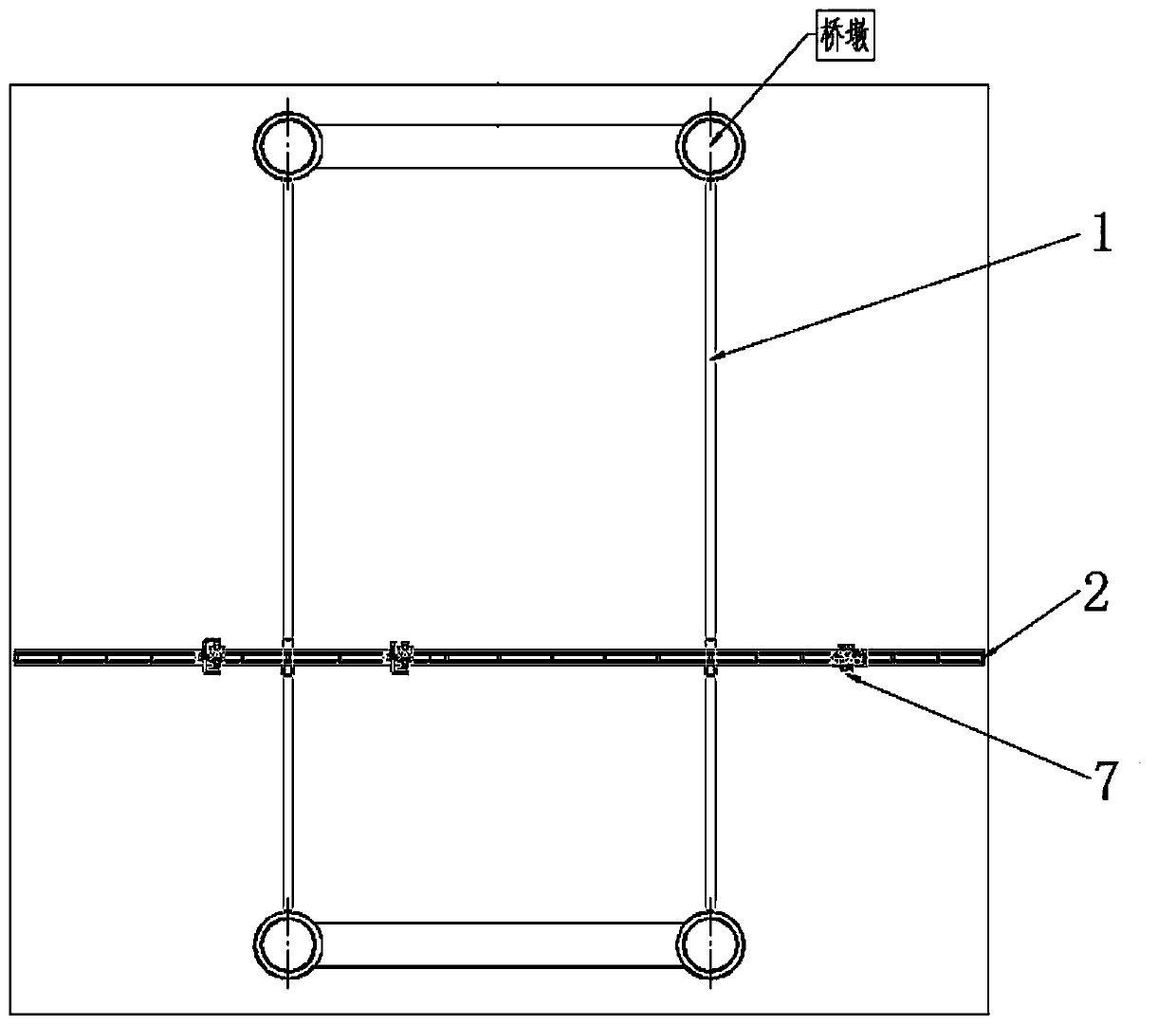
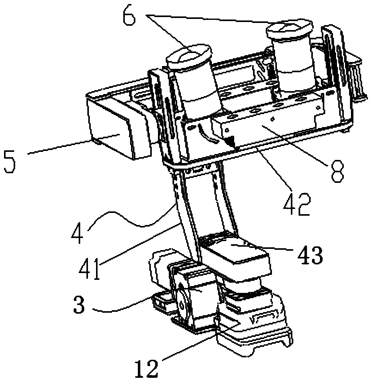
[0032] Such as Figure 1-3 The shown bridge bottom detection device includes two support rails 1 fixed on the bridge, a working platform 2 is slidably connected between the two support rails 1, and at least three detection robots 7 are slidably installed on the working platform 2 It is a group of coordinated detection units; the detection robot 7 includes a walking movement part 3, and the walking movement part 3 is connected with the detection work part 5 through the extension arm 4; the detection work part 5 is equipped with a camera 6; the work platform 2 and the detection robot 7 There are remote data centers with wired or wireless connections. The extension arm 4 includes a base 43 rotatably connected to the running part, the base 43 is articulated to a first articulated arm 41 , the first articulated arm 41 is articulated to a second articulated arm 42 , and the second articulated arm 42 is connected to the working platform 2 . Because there is no GPS signal easily at t...

Embodiment 2

[0038] A bridge bottom detection method, comprising the steps of:

[0039] Step 1. Carry out measurement and three-dimensional modeling of the bottom structure of the bridge body through the remote data center;

[0040]Step 2, according to the characteristics of each box mechanism at the bottom of the bridge body, it is divided into several measurement units; the measurement unit is the bridge area where the quality of the photos taken by the camera 6 reaches a specified level when the detection robot 7 is not adjusted; specifically The photos taken by the camera 6 within a certain focus range are clear, and within the range of the measurement unit, the distance between the camera and the corresponding shooting surface is within the focus range of the camera 6, thereby ensuring the degree of cleaning of the photos taken. Within the scope of the measurement unit, it is only necessary to make the working platform 2 run along the support rail. After each measurement unit is shot,...

Embodiment 3

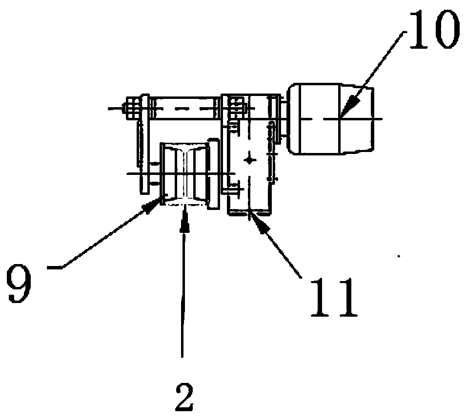
[0044] Such as Figure 5 As shown, in order to realize the fixation of the robot on the working platform 2, the motor 10 is a self-locking motor; the roller 9 is a gear, and there are several teeth that cooperate with the gears along the length direction of the working platform 2; Surface snug setting.


PUM


Abstract

The invention discloses a bridge bottom surface detection device. The bridge bottom surface detection device comprises two support rails which are fixed to a bridge, wherein a working platform is connected between the two support rails in a sliding way; the working platform is connected with a detection unit in which at least detection robots coordinate with one another as a group in a sliding way; the detection robots comprise walking motion parts; the walking motion parts are rotationally connected with detection working parts through extension arms; cameras are arranged on the detection working parts; and the working platform and the detection robots are connected with a remote data center in a wired or wireless manner. Through adoption of the bridge bottom surface detection device andmethod, more than three detection robots are controlled to take photos of box girders and splice the photos simultaneously under the condition of constant shooting posture, so that the splicing difficulty of the taken photos is lowered greatly, and the splicing efficiency and effect are improved. The shooting postures of the cameras can be adjusted according to different conditions through an adjustable extension arm structure.

Description

technical field [0001] The invention belongs to the field of machinery, and in particular relates to a bridge bottom detection device and method. Background technique [0002] Cracks on the bottom surface of the bridge mean that structural damage has occurred inside the bridge, and outside water vapor can easily enter the inside of the bridge, thereby accelerating the corrosion of steel bars, which in turn leads to a decrease in the bearing capacity of the bridge, seriously affecting people's safe travel. Therefore, capturing and inspecting the cracks on the bottom surface of the bridge in time is of great significance for predicting or discovering engineering dangers in time, ensuring the reliable operation of the bridge and prolonging the service life of the bridge. Bridge detection in the prior art mainly includes two methods: manual detection and detection of equipment mounted on the track at the bottom of the bridge. Manual inspection is mainly to observe the cracks at...

Claims


Application Information

Patent Timeline
IPC IPC(8): G01N21/95
CPCG01N21/9515G01N2021/9518
Inventor 陈晓辉万智
Owner 湖南桥康智能科技有限公司
Why Eureka
Try Eureka