UHF RFID reader antenna and switching method

A reader and antenna technology, applied in antennas, antenna arrays, antenna components, etc., can solve problems such as limitations, concentrated energy distribution, and reading blind spots.

Active Publication Date: 2019-09-13
BEIJING XINWANG RUIJIE NETWORK TECH CO LTD
View PDF10 Cites 1 Cited by
  • Summary
  • Abstract
  • Description
  • Claims
  • Application Information

AI Technical Summary

Problems solved by technology

However, its energy distribution in the near-field area (within 30cm) is concentrated or uneven, resulting in a small reading coverage area or a

Method used


Image

  • UHF RFID reader antenna and switching method
  • UHF RFID reader antenna and switching method
  • UHF RFID reader antenna and switching method

Examples


Embodiment Construction

[0038] In order to make the purpose, technical solutions and advantages of the embodiments of the present invention clearer, the technical solutions in the embodiments of the present invention will be clearly and completely described below in conjunction with the drawings in the embodiments of the present invention. Obviously, the described embodiments It is a part of embodiments of the present invention, but not all embodiments. Based on the embodiments of the present invention, all other embodiments obtained by persons of ordinary skill in the art without making creative efforts belong to the protection scope of the present invention.

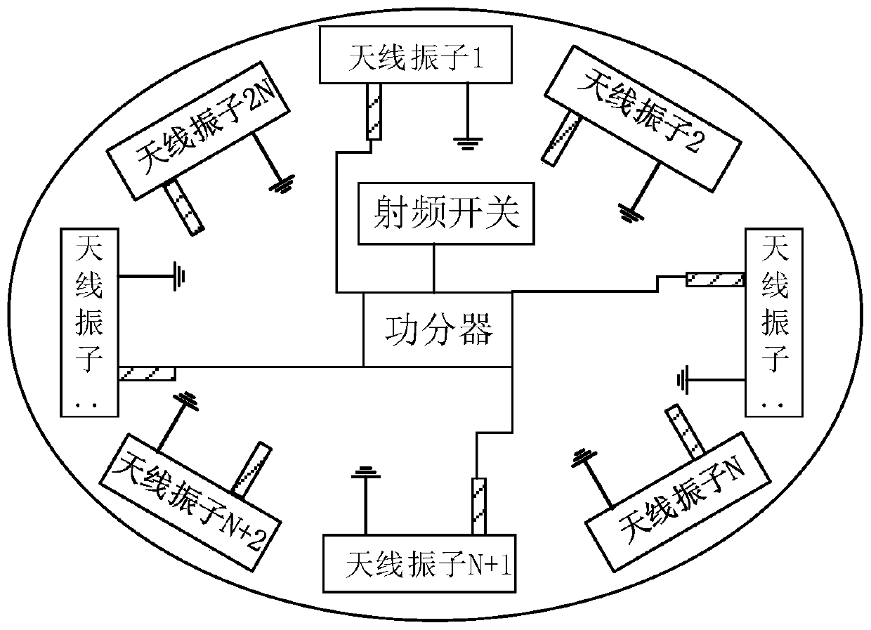
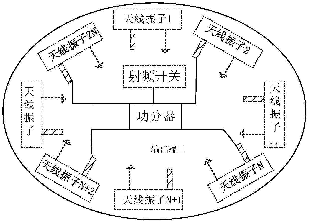
[0039] In order to improve the near-field coverage area of ​​the UHF RFID reader antenna, the embodiment of the present invention adopts that 2N identical antenna elements are evenly distributed on the front (Top) of the printed circuit board (Printed Circuit Board, PCB), respectively on the front and top of the PCB. The reverse side (Bot) is...


PUM


Abstract

The embodiment of the invention provides a UHF RFID reader antenna and a switching method. The antenna comprises the content as follows: 2N same antenna elements are uniformly distributed at the top side of a printed circuit board; N-equal part power dividers and phase extension lines are arranged at the top side and the bottom side of the printed circuit board respectively; radio frequency switches are also arranged; N antenna elements at the top side and the N-equal part power divider and phase extension lines at the top side form a first group of N-arm feed networks which are the same in amplitude and have a phase difference of 360 degrees/N; the other N antenna elements and the N-equal part power divider and phase extension lines at the bottom side form a second group of N-arm feed networks which are the same in amplitude and have the phase difference of 360 degrees/N; and the radio frequency switches control and switch the antenna into a mode of the first group of N-arm feed networks or a mode of the second group of N-arm feed networks. According to the UHF RFID reader antenna, the characteristic of a long identification distance of UHF RFID is maintained, and meanwhile, the identification coverage area of a near-field area is increased under the condition of not increasing the cost and the complexity of a system.

Description

technical field [0001] The embodiment of the present invention relates to the technical field of antennas, in particular to a UHF RFID (ultra-high frequency radio frequency identification) reader antenna and a switching method. Background technique [0002] Radio Frequency Identification (RFID) is an automatic identification technology that automatically identifies target objects through radio frequency signals, and quickly performs item tracking and data exchange. RFID technology does not require manual intervention, can work in various harsh environments, can identify multiple tags at the same time, and is fast and convenient to operate. It is widely used in warehousing logistics, book management, industrial production, transportation, clothing and other fields. [0003] figure 1 It is a schematic structural diagram of the RFID system in the prior art, such as figure 1 As shown, the RFID system is mainly composed of three parts: a reader (Reader), a tag (Tag) and a data ...

Claims


Application Information

Patent Timeline
IPC IPC(8): H01Q1/22H01Q1/38H01Q1/50H01Q21/00H01Q21/20
CPCH01Q1/2216H01Q1/38H01Q1/50H01Q21/0006H01Q21/20
Inventor 权威胡岳挺
Owner BEIJING XINWANG RUIJIE NETWORK TECH CO LTD
Why Eureka
Try Eureka