Ultra-high frequency RFID label antenna for wirelessly measuring dielectric constant

A technology of RFID tags and dielectric constants, applied in the field of RFID tag antennas, can solve the problems of short reading distance of RFID tag antennas, poor parameters, large size of UHF RFID tag antennas, etc.

Active Publication Date: 2020-02-07
NINGBO UNIV
View PDF10 Cites 1 Cited by
  • Summary
  • Abstract
  • Description
  • Claims
  • Application Information

AI Technical Summary

Problems solved by technology

The UHF RFID tag antenna is composed of two straight conductors, the length of each straight conductor is 1 / 4 wavelength, that is, the total length of the UHF RFID tag antenna is half a wavelength, and the two straight conductors do not adopt any folding measures, resulting in a larger UHF RFID tag antenna size
Due to the strong far-field radiation of the dipole RFID tag antenna, the UHF RFID tag antenna is more sensitive to media with different dielectric constants, resulting in lower measurement accuracy. When the UHF RFID tag antenna is placed on a medium with different dielectric constants When on the medium, due to the strong far-field radiation, the resonant frequency of the UHF RFID tag antenna will be greatly shifted, resulting in a mismatch between the impedance of the UHF RFID tag antenna and the impedance of the RF chip. At this time, the UHF RFID tag The S11 parameter of the antenna becomes worse, which eventually makes the reading distance of the RFID tag antenna shorter

Method used


Image

  • Ultra-high frequency RFID label antenna for wirelessly measuring dielectric constant
  • Ultra-high frequency RFID label antenna for wirelessly measuring dielectric constant
  • Ultra-high frequency RFID label antenna for wirelessly measuring dielectric constant

Examples


Embodiment

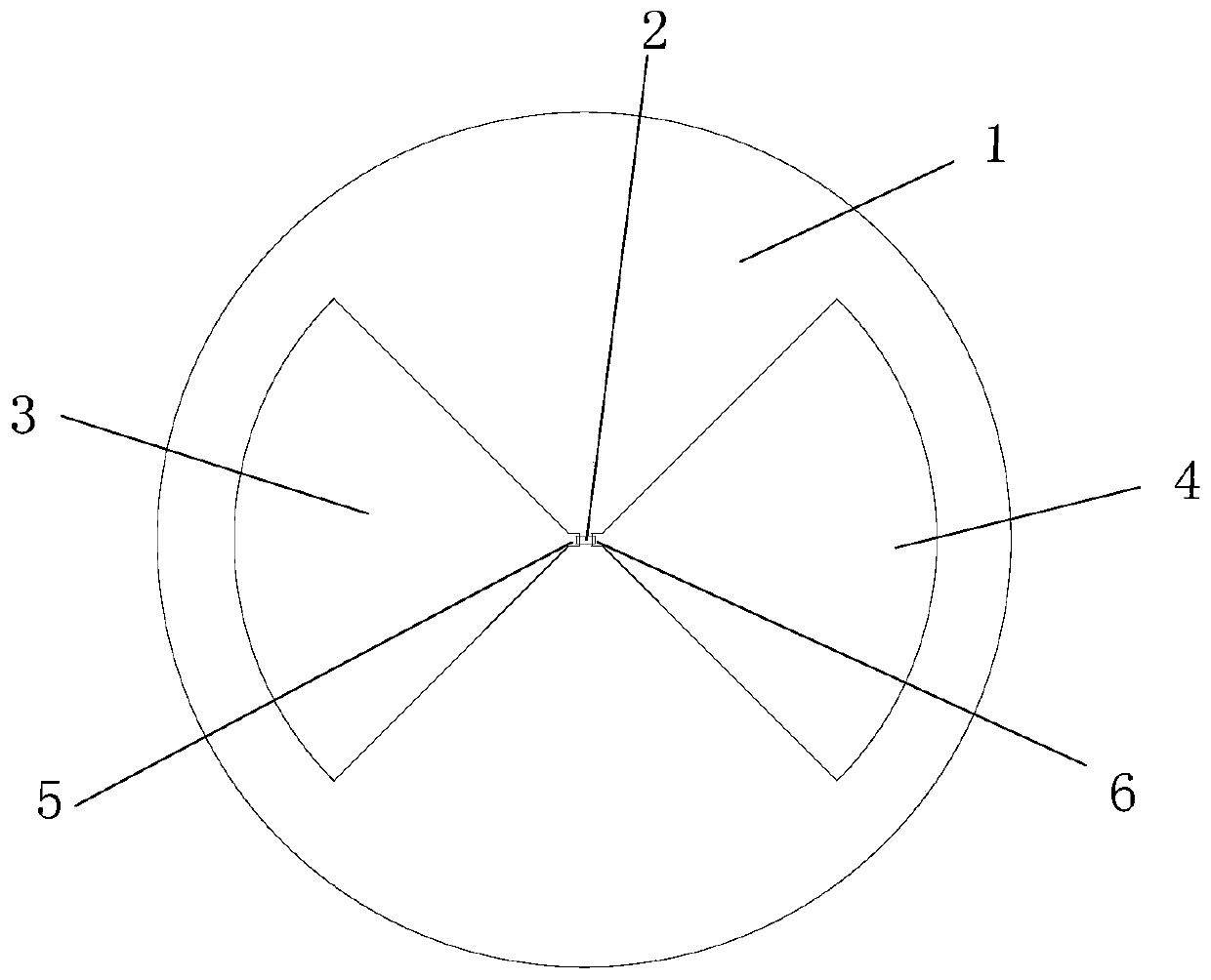
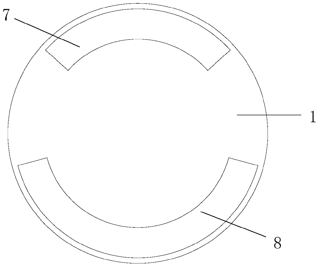
[0012] Example: such as figure 1 and figure 2 As shown, a UHF RFID tag antenna for wirelessly measuring the dielectric constant includes a dielectric substrate 1, a radiation unit arranged on the upper surface of the dielectric substrate 1, and a matching unit arranged on the lower end surface of the dielectric substrate 1; the dielectric substrate 1 is a circle shape, the radius of the dielectric substrate 1 is 32.2 mm; the radiation unit includes a radio frequency chip 2, a first fan-shaped metal layer 3 and a second fan-shaped metal layer 4, and the first fan-shaped metal layer 3 and the second fan-shaped metal layer 4 are attached to the dielectric substrate 1, the left-right symmetrical plane of the dielectric substrate 1 is taken as the reference plane, the center line of the dielectric substrate 1 is located on the reference plane, the first fan-shaped metal layer 3 is located on the left side of the reference plane, and the second fan-shaped metal layer 4 is located o...


PUM

PropertyMeasurementUnit
radiusaaaaaaaaaa
radiusaaaaaaaaaa
angleaaaaaaaaaa

Abstract

The invention discloses an ultra-high frequency RFID label antenna for wirelessly measuring a dielectric constant. The ultra-high frequency RFID label antenna comprises a dielectric substrate, a radiation unit and a matching unit, wherein the radiation unit comprises a radio frequency chip, a first fan-shaped metal layer and a second fan-shaped metal layer, the first fan-shaped metal layer and thesecond fan-shaped metal layer both are attached onto an upper surface of the dielectric substrate, a left-right symmetric surface of the dielectric substrate is used as a reference surface, a centralline of the dielectric substrate is arranged on the reference surface, the first fan-shaped metal layer is arranged at a left side of the reference surface, the second fan-shaped metal layer is arranged at right side of the reference surface, the matching unit comprises a first arc metal layer and a second arc metal layer, the first arc metal layer and the second arc metal layer are attached ontoa lower end surface of the dielectric substrate, a circle center of the first arc metal layer is arranged on a straight line perpendicular to the dielectric substrate and passing through a center ofthe dielectric substrate, and a circle center of the second arc metal layer is arranged on a straight line perpendicular to the dielectric substrate and passing through the center of the dielectric substrate. The ultra-high frequency RFID label antenna has the advantages of relatively small size and relatively long reading distance.

Description

technical field [0001] The invention relates to an RFID tag antenna, in particular to an ultra-high frequency RFID tag antenna for wirelessly measuring dielectric constant. Background technique [0002] RFID tag antennas can be pasted on different objects and interact with RFID readers through radio frequency signals to achieve object identification and tracking purposes. At present, it has replaced traditional barcode scanning technology and has been widely used. The commonly used working frequency bands of RFID tag antennas usually include low frequency band, high frequency band and ultra-high frequency band. Among them, the low frequency band RFID tag antenna and the high frequency band RFID tag antenna work by electromagnetic coupling respectively, the transmission data speed is slow, and the reading distance is short. UHF band RFID tag antennas generally work on the principle of electromagnetic emission, with fast data transmission speed and long reading distance. Ther...

Claims


Application Information

Patent Timeline
Patent Type & Authority Applications(China)
IPC IPC(8): H01Q1/38H01Q1/36H01Q1/22H01Q1/50
CPCH01Q1/2225H01Q1/36H01Q1/38H01Q1/50
Inventor 华昌洲王建业黄雪琴陈益
Owner NINGBO UNIV
Why Eureka
Try Eureka