Washing machine

A technology for washing machines and washing tubs, applied in the field of washing, which can solve the problems of raising the overall center of gravity of the washing tub and the outer tub, destroying the washing tub, and increasing the weight of the upper part of the washing tub, so as to reduce washing water consumption, save washing water consumption, and improve The effect of drainage efficiency

Pending Publication Date: 2019-09-17
QINGDAO HAIER WASHING MASCH CO LTD
View PDF1 Cites 0 Cited by
  • Summary
  • Abstract
  • Description
  • Claims
  • Application Information

AI Technical Summary

Problems solved by technology

[0004] But, there is following problem in above-mentioned scheme, because the washing machine spins at high speed when dehydrating, the water in the clothing is thrown out through the drainage hole 3 ' on the side wall of inner tub 2 ', directly beats on the side wall of outer tub 1 ', easily splashes everywhere, If there is water on the inner wall of the outer barrel for a long time, it is still easy to breed bacteria, which is not conducive to environmental protection
[0005] The Chinese patent application number CN99230455.5 discloses a single-tub water-saving washing machine. A water collecting device is arranged at the mouth of the washing bucket, and the water collecting mouth of the water collecting device is surrounded by the mouth of the washing bucket. The water collection device located at the mouth of the bucket is connected to several drainage pipes, which are arranged symmetrically from top to bottom along the outer wall of the washing bucket. When drying, the water collection device collects the centrifugal water flow due to high-speed rotation and sends it to the The drain is guided downward. Although this structure omits the outer tub, when the washing machine is dehydrating, because the washing water first enters the water collecting device, the water collecting device is a ring structure, and the washing water filled inside is drained downward at different speeds. Destroy the balance of the high-speed rotation of the washing bucket; in addition, after the washing water enters the water collecting device, it is guided to the lower part of the washing bucket to collect and discharge to the center, which is not conducive to drainage, making it difficult to discharge when concentrated in the water collecting chamber under the action of centrifugal force, resulting in concentrated washing water At the upper end of the washing bucket, the weight of the upper part of the washing bucket is increased, which further destroys the balance, especially when there is a lot of residual water in the washing bucket, most of the washing water is concentrated in the water collecting chamber and is not discharged, and the distance between the washing bucket and the outer bucket is increased. The overall center of gravity produces great vibration noise and increases the working load of the dehydration motor, which is easy to damage the motor

Method used


Image

  • Washing machine
  • Washing machine
  • Washing machine

Examples


Embodiment 1

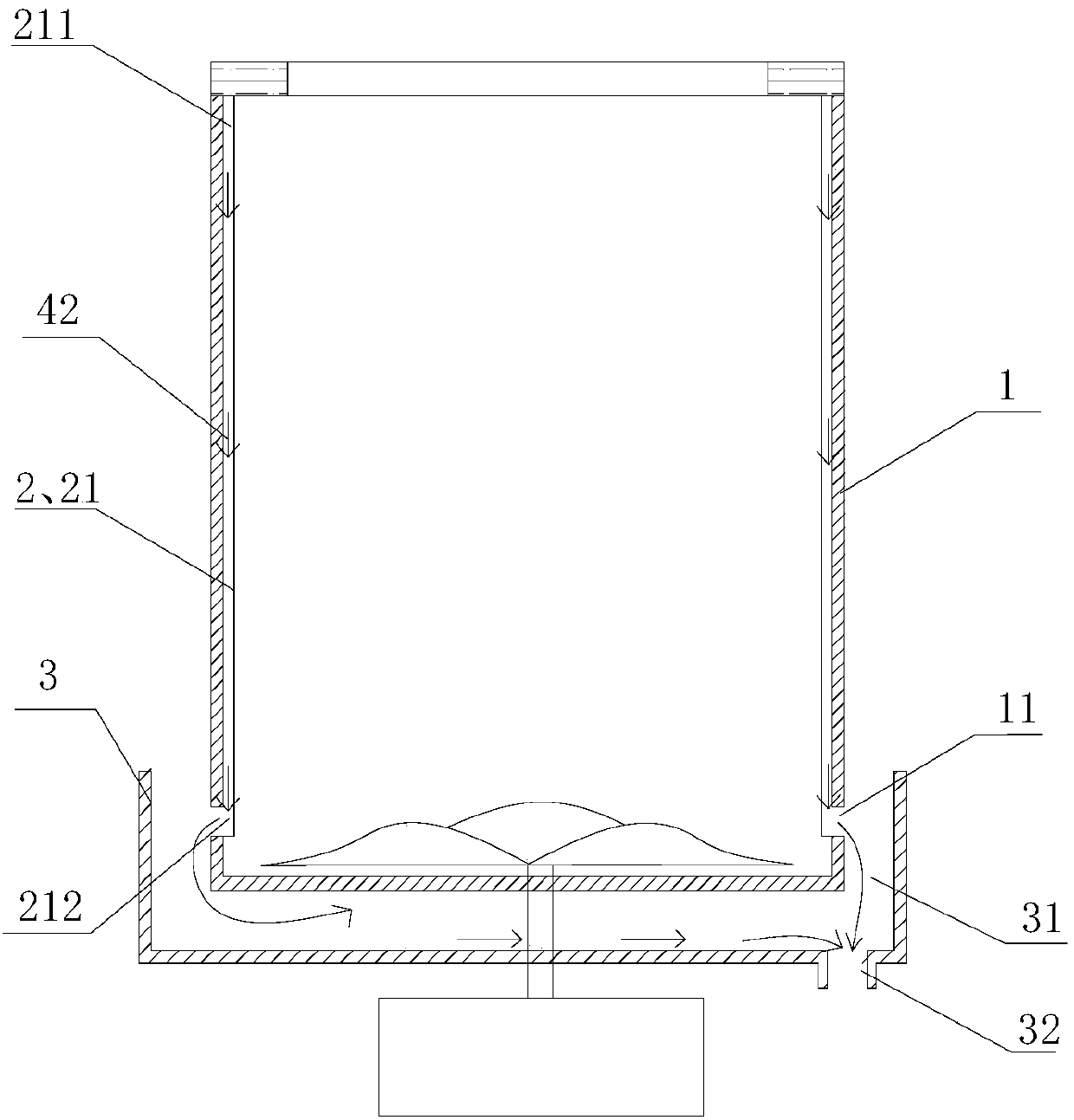
[0062] Such as figure 2 As shown, the drainage assembly 2 described in this embodiment includes a first drainage channel 21 that is located inside the circumferential area where the peripheral wall of the washing tub 1 is located and conducts water from top to bottom. It enters into the first drainage channel 21 along the circumference of the washing tub, and the lower part is a water outlet 212 for draining water to the outside of the washing tub.

Embodiment 2

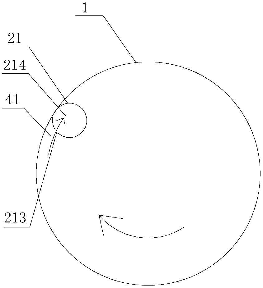
[0064] Such as figure 2 As shown, on the basis of Embodiment 1, the drainage assembly 2 of this embodiment also includes a first water outlet 11 arranged on the peripheral wall of the washing tub 1, or the first water outlet is arranged on the bottom wall, such as image 3 with Figure 4 As shown, the first drainage channel 21 is installed on the inner peripheral wall of the washing tub 1, the first drainage channel 21 is covered with the first drainage port 11 at the lower part, and the water inlet 213 is provided at the upper part and is defined from the water inlet 213 down to the The second path 42 of the first water outlet 11 .

[0065] Further, such as image 3 As shown, the first drainage channel 21 is an independent structure, the upper part has a water inlet 213 corresponding to the radial side wall, the interior has a water guiding chamber 214 forming a second path, and the lower part has a outlet, or, if Figure 4 As shown, the first drainage channel 21 is a co...

Embodiment 3

[0069] Such as Figure 5 As shown, on the basis of Embodiment 1, the surrounding wall of the washing tub 1 in this embodiment is provided with at least one groove 12 with an opening along the up and down direction, and the groove bottom of the groove 12 protrudes inwardly from the inside of the washing tub 1. The peripheral wall, the opening of the groove 12 is covered with a cover plate 13, which constitutes the first drainage channel 21, and the groove 12 has a second path 42 for leading water from top to bottom (see figure 2 ).

[0070] Preferably, the upper side wall of the groove 12 has a water inlet 213 , and the lower part of the cover plate 13 has a water outlet.

[0071] Also preferably, the water inlet 213 is arranged on the radial side wall of the groove 12 that is consistent with the dehydration rotation direction of the washing tub, and the opening direction of the water inlet 213 is consistent with the dehydration rotation direction of the washing tub 1 .

[0...


PUM


Abstract

The invention discloses a washing machine. The washing machine comprises a tank body and a washing bucket rotatably arranged in the tank body, wherein the washing bucket is of a bucket structure used for containing water during washing, the peripheral wall of the washing bucket is provided with a drainage assembly used for discharging water in the washing bucket to the outside of the washing bucket, the water is discharged to the outside of the washing bucket through a drainage way matched with the drainage assembly, the drainage way comprises a first way guiding the water in the washing bucket into the drainage assembly in the radial direction or circumferential direction of the washing bucket and a second way guiding the water to be discharged downward to the outside of the washing bucket in the drainage assembly. The washing machine utilizes the drainage assembly arranged on the peripheral wall of the washing bucket to improve the drainage efficiency through the radial or circumferential rapid and directional drainage.

Description

technical field [0001] The invention belongs to the field of washing, and in particular relates to a washing machine. Background technique [0002] The traditional fully automatic pulsator washing machine generally consists of an inner tub, an outer tub, a vibration-damping component and a power system. During washing and dehydration, the inner tub rotates relative to the outer tub to make the clothes interact with the washing water to achieve the purpose of washing or dehydrating the clothes. , wherein, the outer barrel is installed on the outside of the inner barrel to provide support for the inner barrel, the outer barrel is used as a water bucket, and the side walls of the inner barrel are evenly distributed with drainage holes, so that the inner and outer barrels are connected. During the washing process, the clothes are placed in the inner tub, and the water levels of the two tubs are the same, but the outer tub does not touch the clothes. The outer tub of the existing...

Claims


Application Information

Patent Timeline
Patent Type & Authority Applications(China)
IPC IPC(8): D06F23/04D06F39/08
CPCD06F39/08D06F39/083D06F23/04
Inventor 吕佩师许升吕艳芬
Owner QINGDAO HAIER WASHING MASCH CO LTD
Why Eureka
Try Eureka