Pipe joint fastener for preventing thermal expansion and cold contraction

A technology of pipe joints, thermal expansion and contraction, applied in the direction of pipes/pipe joints/fittings, pipeline systems, through components, etc. Avoid pulling effects

Active Publication Date: 2019-09-17
浙江环台精密机械股份有限公司
View PDF10 Cites 4 Cited by
  • Summary
  • Abstract
  • Description
  • Claims
  • Application Information

AI Technical Summary

Problems solved by technology

[0003] The biggest problem faced by the existing pipe joints is the heat expansion and contraction of the pipe. When the pipe is heated, the pipe will stretch and expand, so it is easy to pull and squeeze the joint. , so the joints are prone to loosening and damage, and when the pipe is cold and shrinks, the gap with the joint will increase, affecting the sealing effect and prone to leakage, and the traditional joint does not detect the thermal expansion and contraction of the pipe , the degree of thermal expansion and contraction cannot be observed, and the influence of thermal expansion and contraction on the pipeline cannot be analyzed
[0004] In order to solve the above problems, the inventor provided a pipe joint fastener that prevents thermal expansion and contraction. When the pipe is deformed due to thermal expansion and contraction, it can maintain the sealing effect on the inner and outer sides of the pipe, and the gap between the pipe and the joint There will be no offset, thereby avoiding the problems of loose joints and decreased sealing performance. At the same time, the deformation of the pipeline can be observed intuitively, which is conducive to the analysis of the influence of the deformation of the pipeline on the joints, and provides a basis for future maintenance. basis

Method used


Image

  • Pipe joint fastener for preventing thermal expansion and cold contraction
  • Pipe joint fastener for preventing thermal expansion and cold contraction
  • Pipe joint fastener for preventing thermal expansion and cold contraction

Examples


Embodiment Construction

[0021] The following will clearly and completely describe the technical solutions in the embodiments of the present invention with reference to the accompanying drawings in the embodiments of the present invention. Obviously, the described embodiments are only some, not all, embodiments of the present invention. Based on the embodiments of the present invention, all other embodiments obtained by persons of ordinary skill in the art without making creative efforts belong to the protection scope of the present invention.

[0022] The embodiment of the pipe joint fastener preventing thermal expansion and contraction is as follows:

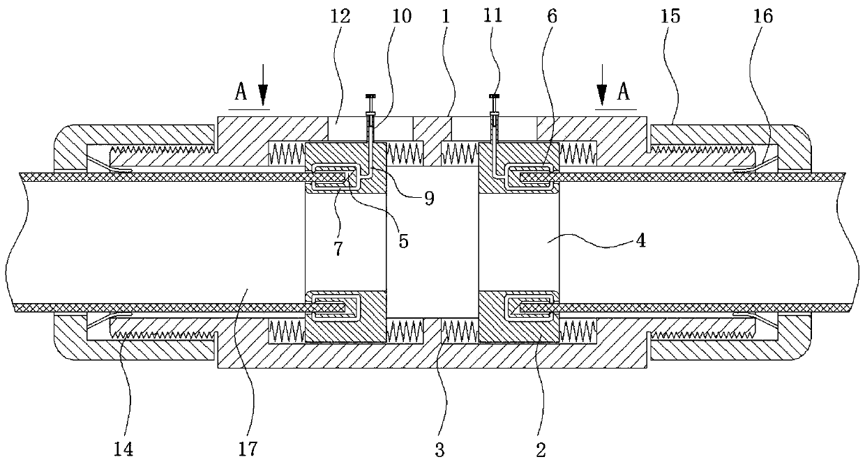
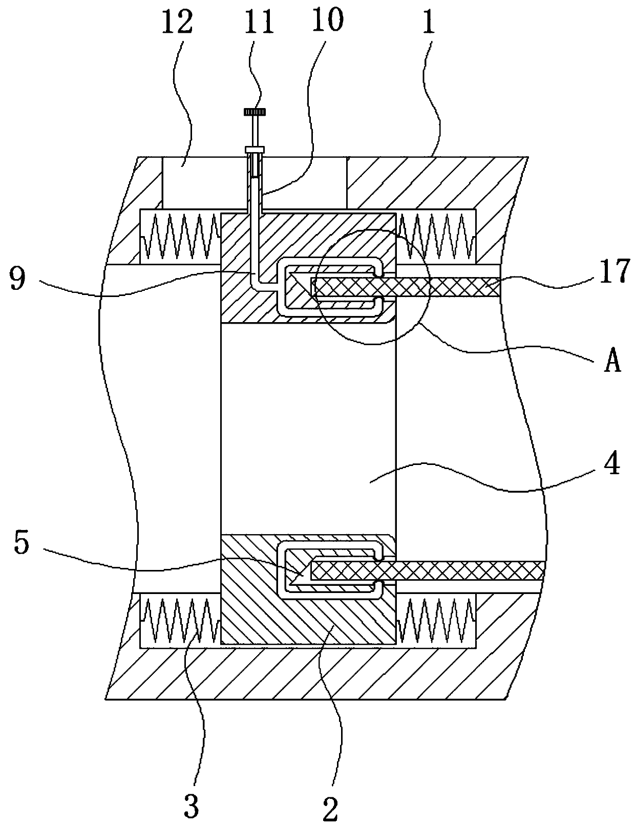
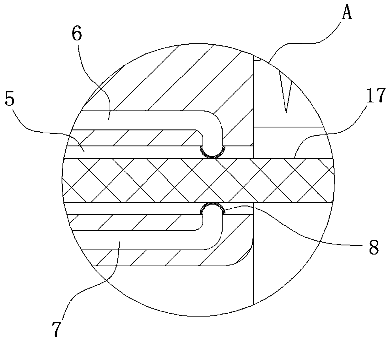
[0023] see Figure 1-4 , pipeline joint fasteners to prevent thermal expansion and cold contraction, including joint 1, positioning ring 2, spring 3, round hole 4, groove 5, upper oil pipe 6, lower oil pipe 7, rubber sleeve 8, oil delivery pipe 9, oil injection rod 10 , Bolt plug 11, trunking 12, marking 13, external thread 14, fixing seat 15, extrus...


PUM


Abstract

The invention provides a pipe joint fastener for preventing thermal expansion and cold contraction, and relates to the technical field of pipe joints. The pipe joint fastener for preventing thermal expansion and cold contraction comprises a joint, the inner portion of the joint is slidably connected with a positioning ring, the two sides of the positioning ring are fixedly connected with springs, the center of the positioning ring is provided with a circular hole, grooves are formed in the sides, facing the left and right ends of the joint, of the positioning ring, and an upper oil pipe and a lower oil pipe are arranged on the upper and lower sides of the grooves in the positioning ring. According to the pipe joint fastener for preventing thermal expansion and cold contraction, the sealing effect on the inner and outer sides of a pipe can be maintained when the pipe is deformed due to thermal expansion and cold contraction, no deviation occurs between the pipe and the joint, the problems of looseness of the joint and decreasing of the sealing performance are solved, meanwhile, the deformation of the pipe can be visually observed, analysis of deformation of the pipe on the joint is facilitated, and a basis is provided for future maintenance.

Description

technical field [0001] The invention relates to the technical field of pipeline joints, in particular to pipeline joint fasteners for preventing thermal expansion and cold contraction. Background technique [0002] With the progress of society and the continuous improvement of living standards, the application of various pipes brings convenience to people's lives, and also makes pipes an indispensable product in modern life, and pipe fittings are becoming more and more popular. These occasions are widely used, among which, as an important component of pipe fittings, pipe joints can firmly connect the main bodies of pipes together, so people are paying more and more attention to the performance and practicability of pipe joints. [0003] The biggest problem faced by the existing pipe joints is the heat expansion and contraction of the pipe. When the pipe is heated, the pipe will stretch and expand, so it is easy to pull and squeeze the joint. , so the joints are prone to loo...

Claims


Application Information

Patent Timeline
Patent Type & Authority Applications(China)
IPC IPC(8): F16L19/02F16J15/46F17D5/00
CPCF16J15/46F16L19/0206F16L19/0212F16L19/0237F17D5/00
Inventor 金法银
Owner 浙江环台精密机械股份有限公司
Why Eureka
Try Eureka