Converter fault handling method, readable storage medium and converter

A fault handling method and converter technology, applied in the direction of converting AC power input to AC power output, output power conversion device, electrical components, etc., can solve problems such as damage, damage to full-control switching devices, etc.

Active Publication Date: 2021-01-15
SHENZHEN HOPEWIND ELECTRIC CO LTD
View PDF7 Cites 0 Cited by
  • Summary
  • Abstract
  • Description
  • Claims
  • Application Information

AI Technical Summary

Problems solved by technology

[0010] One of the technical problems to be solved by the present invention is to provide a method for handling converter faults, which overcomes the defects in the prior art that may cause damage or potential damage to the full-control switching device when the converter is faulty
[0011] The second technical problem to be solved by the present invention is to provide a readable storage medium, which stores the software of the above-mentioned converter fault handling method, which is convenient for the use of the converter and overcomes the possibility of converter failure in the prior art. Defects such as damage or potential damage to full-control switching devices
[0012] The third technical problem to be solved by the present invention is to provide a converter, which uses the above-mentioned readable storage medium, so as to overcome the possible damage or potential failure of the full-control switching device in the prior art when the converter fails. Defects such as damage

Method used


Image

  • Converter fault handling method, readable storage medium and converter
  • Converter fault handling method, readable storage medium and converter
  • Converter fault handling method, readable storage medium and converter

Examples


Embodiment 1

[0087] like Figure 5 As shown, the converter fault handling method of the present invention includes the following steps:

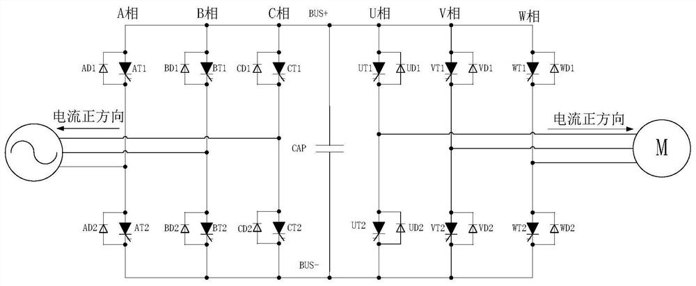
[0088] Step 1, the controller U3 runs the main program, that is, detects the main circuit U1 of the converter, and determines whether the main circuit U1 is faulty.

[0089] Step 2: When the controller U3 judges that the main circuit U1 is not faulty, return to step 1; when the controller judges that the main circuit U1 is faulty, enter the next step.

[0090] Step 3: The controller U3 determines the faulty phase unit and the non-faulty phase unit of the main circuit U1 of the converter.

[0091] Step 4: The controller U3 sends a control command to turn off the fully-controlled switching device of the non-faulty phase unit of the main circuit U1 of the converter, and keeps the switching state of the fully-controlled switching device of the faulty phase unit of the main circuit U1 of the converter. Change.

Embodiment 2

[0093] like Figure 6 As shown, the converter fault handling method of the present invention includes the following steps:

[0094] Steps 1 to 4 of this embodiment are the same as those of Embodiment 1.

[0095] The "fault" in step 1 includes direct faults and non-direct faults, and "judging whether the main circuit U1 has a fault" refers to judging whether the main circuit U1 has a direct fault or a non-direct fault. The failed phase unit is called the faulted phase unit, and the remaining unfaulted phase units are called non-faulted phase units, the same below.

[0096] Step 5: When a non-shoot-through fault is detected but a shoot-through fault is not detected, within the delay time Tdelay, the controller U3 detects the faulty phase unit and determines whether a shoot-through fault occurs in the faulty phase unit.

[0097] Step 6. When the controller U3 detects that the faulty phase unit has a through fault, the controller U3 issues a command to continue to maintain the c...

Embodiment 3

[0101] like Figure 7 As shown, the converter fault handling method of the present invention includes the following steps:

[0102] Steps 1 to 4 of this embodiment are the same as those of Embodiment 1.

[0103]The "fault" in step 1 includes direct faults and non-direct faults, and "judging whether the main circuit U1 has a fault" refers to judging whether the main circuit U1 has a direct fault or a non-direct fault.

[0104] Step 5: When a non-shoot-through fault is detected but a shoot-through fault is not detected, within the delay time Tdelay, the controller U3 detects the faulty phase unit and determines whether a shoot-through fault occurs in the faulty phase unit.

[0105] Step 6: When the controller U3 does not detect the through fault of the faulty phase unit, the controller U3 issues a command to turn off the full-control switching device of the faulty phase unit of the converter.

[0106] When the controller U3 detects the through fault of the faulty phase unit, a...


PUM


Abstract

The invention discloses a converter fault processing method, a readable storage medium and a converter. The converter comprises a converter main loop U1 and a controller U3; the method comprises the steps that: SP1, a U3 detects a U1 and determines whether the U1 has a fault or not; SP2, when a U2 determines that the U1 has no fault, the process returns to the SP1; when the U2 determines that the U1 has a fault, the next step is performed; SP3, the U3 determines the failed and non-failed phase cells of the U1; SP4, the U3 turns off the fully controlled switching device of the non-failed phase cell of the U1 to keep the fully controlled switching device of the failed phase cell of the U1. The converter fault processing method can reduce fault loss, can reduce fault occurrence range, can shorten maintenance time of the converter and can improve equipment availability.

Description

technical field [0001] The invention relates to the technical field of power electronics, in particular to a converter fault processing method, a readable storage medium and a converter. Background technique [0002] Turn-off thyristors GTO, gate commutated thyristors GCT, and integrated gate commutated thyristors IGCT are commonly used full-control switching devices that constitute AC-DC-AC converters. Taking IGCT as an example, IGCT is a high-voltage, high-power, fast-acting power electronic device, which can be used to form two-level, three-level and multi-level IGCT converters. It has become an important development direction of AC frequency conversion speed control devices in the medium and high voltage field. [0003] like figure 1 Shown is a two-level AC-DC-AC converter composed of fully controlled switching devices GTO or GCT or IGCT. In the figure, AT1, AT2, BT1, BT2, CT1, and CT2 are full-control switch devices GTO or GCT or IGCT, AD1, AD2, BD1, BD2, CD1, CD2 ar...

Claims


Application Information

Patent Timeline
Patent Type & Authority Patents(China)
IPC IPC(8): H02M5/45
CPCH02M5/4505
Inventor 王武华霍明李海龙郑大鹏周党生
Owner SHENZHEN HOPEWIND ELECTRIC CO LTD
Why Eureka
Try Eureka