
sounder

A sound generator and vibration system technology, applied in the direction of sensors, transducer diaphragms, sensor types, etc., can solve the problems of poor gluing between the voice coil and the diaphragm, affecting the performance of the sound generator, impact, etc., to improve the pure tone. Good performance, good bonding, and improved reliability

Active Publication Date: 2021-10-19
AAC TECH PTE LTD
View PDF10 Cites 0 Cited by
  • Summary
  • Abstract
  • Description
  • Claims
  • Application Information

AI Technical Summary

Problems solved by technology

[0006] In view of the fact that the sound generator in the related art is affected by the structure of the diaphragm body, there will be poor gluing or glue overflow at the joint between the voice coil and the diaphragm, and the distance between the voice coil and the magnetic frame will also be reduced. When the voice coil vibrates, it may hit the magnetic frame, thereby affecting the technical problem of the performance of the sounder. The invention provides a sounder with better reliability

Method used


Image

  • sounder
  • sounder
  • sounder

Examples


Embodiment 1

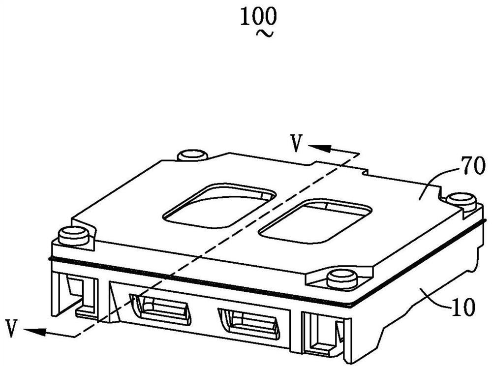
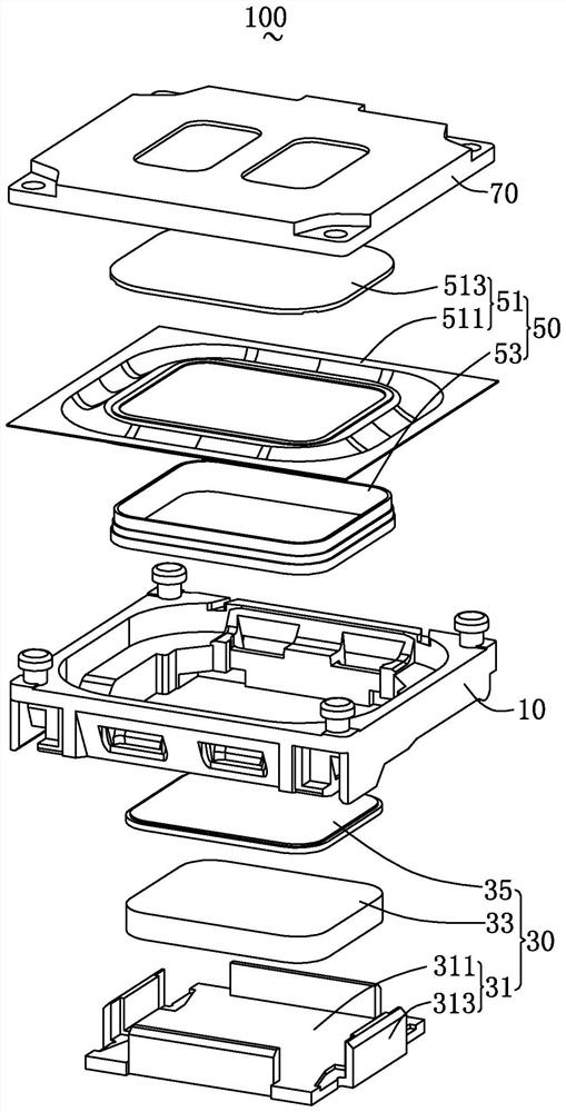
[0031] Please refer to figure 1 with figure 2 . The present invention provides a sound generator 100 , which includes a frame 10 , a magnetic circuit system 30 and a vibration system 50 accommodated in the frame 10 , and a front cover 70 covering the frame 10 .

[0032] The magnetic circuit system 30 is used to drive the vibration system 50 to vibrate and produce sound. The magnetic circuit system 30 includes a magnetic yoke 31, a magnetic steel 33 assembled on the magnetic yoke 31, and a magnetic steel 33 stacked on the magnetic steel 33. The upper pole core 35. The yoke 31 includes a bottom wall 311 and a side wall 313 bent and extended from the bottom wall 311 , and the magnetic steel 33 is spaced apart from the side wall 313 to form a magnetic gap.

[0033] The vibration system 50 includes a diaphragm 51 for vibrating and sounding and a voice coil 53 for driving the diaphragm 51 to vibrate and sound, and the voice coil 53 is partially inserted into the magnetic gap.

...

Embodiment 2

[0043] Please refer to the collection Figure 7 to Figure 10 . The present invention provides a sounder 200, the structure of the sounder 200 is basically the same as that of the sounder 100 in Embodiment 1, the difference lies in:

[0044] In this embodiment, the receiving groove 1516 is recessed from the first surface 1514 toward the second surface 1515 and is disposed through the second surface 1515 . That is, it can be understood that the dome in this embodiment is a split structure. Specifically, the dome includes a dome body 1517 located in the middle and a dome edge 1518 located at the edge. The dome body 1517 and the dome The top edges 1518 are arranged at intervals to form the receiving grooves 1516 . Wherein, the dome edge 1518 includes two first parts 1520 and two second parts 1521 opposite to each other. The second part 1521 is set facing the two short axis sides of the dome body 1517, so that the bonding surface between the first part 1520 and the long axis sid...


PUM


Abstract

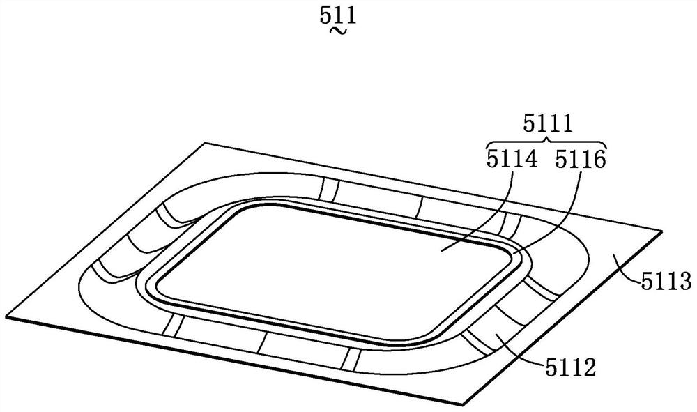
The invention provides a sounder. The sounder includes a vibration system and a magnetic circuit system that drives the vibration system to vibrate and sound, the vibration system includes a diaphragm and a voice coil that drives the diaphragm to vibrate and sound, and the diaphragm includes a fixed diaphragm A body and a dome, the diaphragm body includes a vibrating part fixed to the dome and a ring part bent and extended from the edge of the vibrating part, the vibrating part includes a main body and a part close to the main body One side of the magnetic circuit system is recessed in a direction away from the magnetic circuit system and has a recessed portion with a groove, and the voice coil part is accommodated in the groove and fixedly connected with the vibrating part. Compared with the related art, the reliability of the sound generator provided by the invention is better.

Description

【Technical field】 [0001] The invention relates to the field of acoustic-electric conversion, in particular to a sound generator. 【Background technique】 [0002] With the rapid development of mobile communication technology in recent years, consumers are increasingly using mobile communication devices with voice functions, such as portable phones, handheld game consoles, laptop computers, laptop computers, multimedia players and through Other devices that communicate over public or private communication networks. And sound generator is as the playing device of voice, and its design quality directly influences the performance of mobile communication equipment. [0003] In the related art, the sound generator includes a vibration system and a magnetic circuit system that drives the vibration system to vibrate and sound. The vibration system includes a diaphragm and a voice coil that drives the diaphragm to vibrate. The diaphragm includes a stacked and fixed diaphragm body and ...

Claims


Application Information

Patent Timeline
Patent Type & Authority Patents(China)
IPC IPC(8): H04R7/12H04R7/18H04R9/04
CPCH04R7/127H04R7/18H04R9/04
Inventor 曾健
Owner AAC TECH PTE LTD
Learn More