Intestinal tract fixing and traction mechanism

A traction mechanism and intestinal technology, applied in the field of medical devices, can solve the problems of difficulty in feeding the anus to the surgical site, affecting the progress of the operation, tingling in the intestines, etc., and achieve the effects of shortening the operation time, real-time lubrication, and improving the operation efficiency.

Inactive Publication Date: 2019-09-20
汤文凯
8 Cites 2 Cited by

AI-Extracted Technical Summary

Problems solved by technology

However, this solution still has the following problems: (1) A slope is provided at one end of the fixed tube, although it can make the end more easily penetrate the inner side of the intestinal tract, but because the end is in the shape of a spike, it is easier to cause stinging pain to the intestine (injury), thereby affe...

Method used

Connecting pipe 3 (in order to illustrate clearly in Fig. 1,2 adopt dotted line to show) head end and upper end intestines suture are fixed specifically as: on the pipe cross section of described connecting pipe 3 head end, be provided with several groups of evenly distributed wire slots 3a, the suture 3b is set in the wire groove 3a, and the suture 3b is stored in the wire groove 3a through the limit cooperation of the wire knot 3c and the wire groove 3a, so that different amounts can be accommodated according to the intestinal structure of different patients ( length), and because the suture 3b is stored in the ...

Abstract

The invention relates to the technical field of medical instruments, in particular to an intestinal tract fixing and traction mechanism which comprises a positioning pipe, a pushing hose, a connecting pipe and a pushing head. The pushing hose is positioned in the positioning pipe, the middle of the pushing hose is provided with a spiral pipe, the head end of the pushing hose is provided with a flat and straight pipe I, the tail end of the pushing hose is provided with a flat and straight pipe II, the flat and straight pipe II penetrates a fixed cover and then is exposed, one end of the flat and straight pipe I is sealed, passes the inside of the connecting pipe, penetrates the inside of the pushing head and then is movably connected with the pushing head, a plurality of penetration holes are formed in the periphery of the pushing head, a pushing sheet is mounted at the end of the flat and straight pipe I in the pushing head, a limit ring is arranged on the flat and straight pipe I outside the pushing head in a sleeving manner, a suture line is arranged at the head end of the connecting pipe, and a double-ring fixing structure is arranged at the tail end of the connecting pipe. The intestinal tract fixing and traction mechanism is simple and ingenious to set and convenient to operate, injury to human bodies is avoided, the connecting pipe can be rapidly conveyed to an operation position of a patient, operation time is shortened, operation efficiency is improved, and the connecting pipe is more closely connected with an upper intestinal tract and a lower intestinal tract.

Application Domain

Technology Topic

Suture lineEngineering +4

Image

  • Intestinal tract fixing and traction mechanism
  • Intestinal tract fixing and traction mechanism
  • Intestinal tract fixing and traction mechanism

Examples

  • Experimental program(1)

Example Embodiment

[0027] The technical solutions in the embodiments of the present invention will be clearly and completely described below in conjunction with the accompanying drawings in the embodiments of the present invention. Obviously, the described embodiments are only a part of the embodiments of the present invention, rather than all the embodiments. Based on the embodiments of the present invention, all other embodiments obtained by those of ordinary skill in the art without creative work shall fall within the protection scope of the present invention.
[0028] See Figure 1~5 , The present invention provides a technical solution:
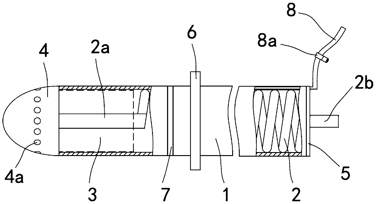
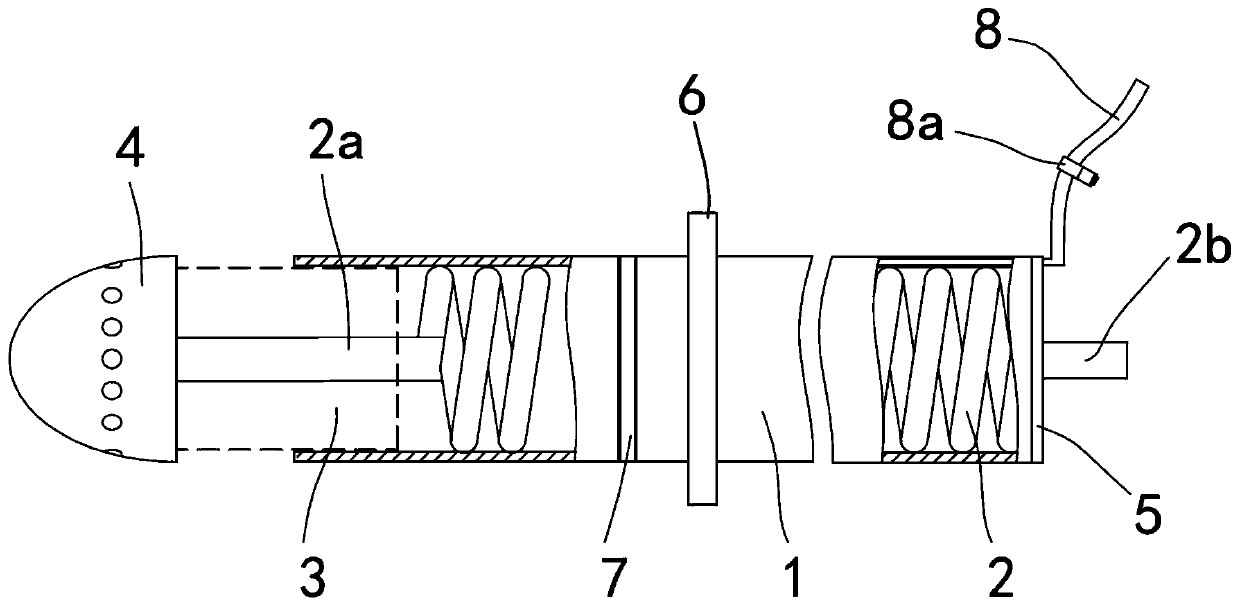
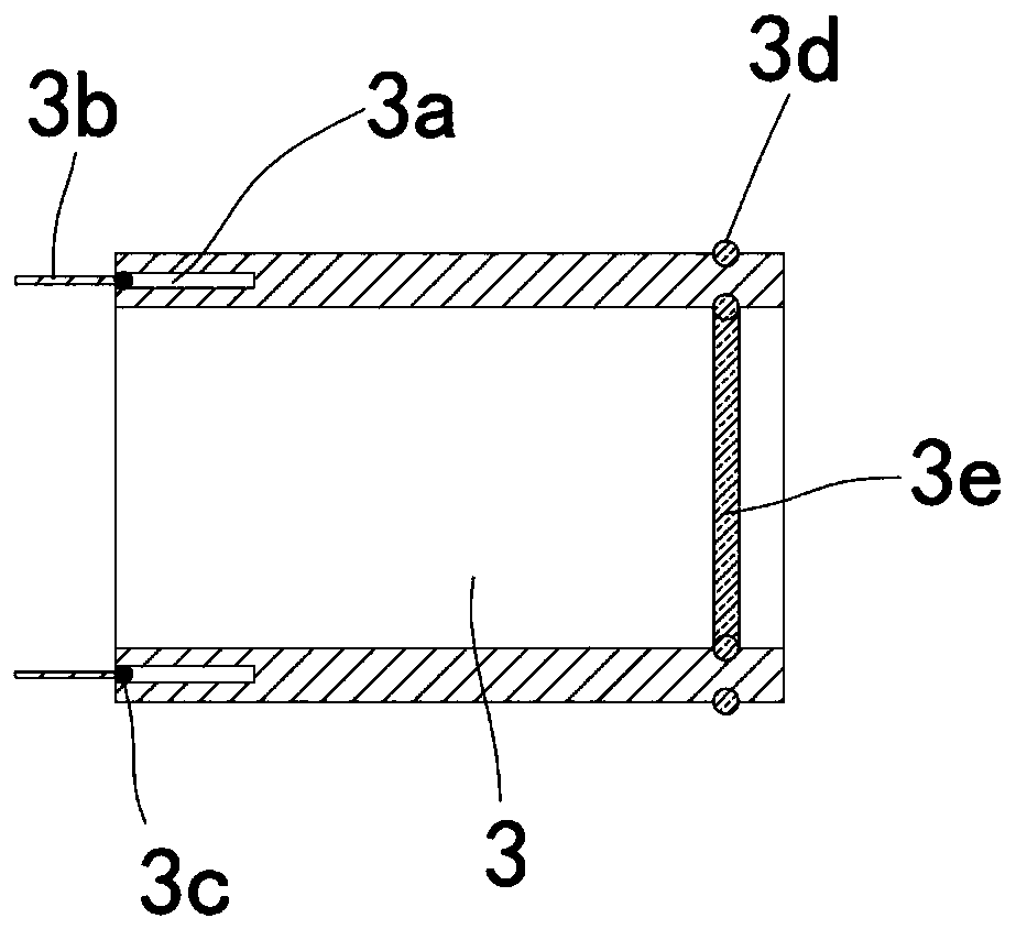
[0029] An intestinal fixed traction mechanism, comprising a positioning tube 1, a propulsion hose, a connecting tube 3, and a propulsion head 4. The tail end of the positioning tube 1 is equipped with a fixed cover 5, and the propulsion hose is located in the positioning tube 1. The middle part of the push hose is a spiral tube 2, the head end is a straight tube I2a, and the tail end is a straight tube II2b. The straight tube II2b penetrates the fixed cover 5 and is exposed. The connecting tube 3 is located at the head of the positioning tube 1. The end of the tube, and the connecting tube 3 penetrates through the inside of the propelling head 4 and then is movably connected. The propelling head 4 is provided with a number of permeation holes 4a in the circumferential direction. The number of permeation holes 4a depends on the actual situation and is located in the propelling head 4. The end of the inner straight tube I2a is equipped with a push piece 2c, and the straight tube I2a outside the pushing head 4 is sleeved with a limiting ring 2d. The straight tube I2a passes through the connecting tube 3 and is connected to the pushing head 4. The propelling head 4 is a shell shaped like a bullet, and the housing is filled with lubricating oil. The propelling head 4 drives the connecting tube 3 to move to the surgical site (upper intestine, lower intestine) to move more quickly, Moreover, the shape of the end of the propelling head 4 is similar to the head of a bullet, so it will not cause irritation (injury) to the intestines, ensuring the smooth progress of the operation. The connecting tube 3 has a suture 3b at the head end and a suture thread 3b at the tail end. With the double-ring fixing structure, the suture thread 3b can suture and fix the first end of the connecting tube 3 and the upper intestine, and the double-ring fixing structure can suture and fix the tail end of the connecting tube 3 and the interface of the lower intestine.
[0030] When the pusher head 4 drives the connecting tube 3 to move to the operation site, since the end of the straight tube I2a is movably connected with the pusher head 4, the two can move relative to each other, and then under the cooperation of the stop ring 2d, the flat tube The end of I2a can drive the push plate 2c to reciprocate in the propulsion head 4, that is, the housing. The push plate 2c squeezes the lubricating oil in the housing from the penetration hole 4a to realize the continuous lubrication of the propulsion head 4 and the intestinal movement process. It greatly speeds up pushing the connecting tube 3 to the operation site, and avoids intestinal injury.
[0031] Connecting pipe 3 (for clarity figure 1 , 2 (Shown in dashed lines) The head end and the upper end of the intestine are sutured and fixed specifically: a plurality of sets of evenly distributed thread grooves 3a are opened on the tube section of the first end of the connecting tube 3, and the suture threads 3b are arranged in the thread groove 3a, And through the limited cooperation of the thread knot 3c and the thread groove 3a, the suture thread 3b is accommodated in the thread groove 3a, so that different amounts (length) of suture thread 3b can be accommodated according to the intestinal structure of different patients, and because of the use of the suture thread 3b Stored in the wire slot 3a, it can be sutured as soon as the connecting tube 3 reaches the surgical site, which shortens the operation time, improves the operation efficiency, and does not interfere with the movement of the pusher 4; image 3 As shown, a knot 3c is tied at the end of the suture 3d, so that when the other end of the suture 3d is used, the knot 3c can drive the head end of the connecting tube 3 to be sutured and fixed with the upper intestine. The number of grooves 3a depends on the actual use. However, of course, the unknotted end of the suture 3d can be placed in the connecting tube 3 in the initial state.
[0032] The double-ring fixing structure includes an outer ring rubber tube 3d and an inner ring rubber tube 3e, wherein: the outer ring rubber tube 3d is embedded in the outer wall of the end of the connecting tube 3, and the inner ring rubber tube 3e is embedded in the connecting tube 3 On the inner wall of the tail end, when the tail end of the connecting tube 3 is connected to the lower intestinal port, first remove the outer ring rubber tube 3d from the connecting tube 3, and then put the lower intestinal port on the end of the connecting tube 3, and then The outer ring rubber tube 3d is installed back to its original position. At this time, gas is injected into the inner ring rubber tube 3e (or also the outer ring rubber tube 3d), so that the inner ring rubber tube 3e is slightly expanded outward, so that the end of the connecting tube 3 Closely connected with the intestine, the outer ring rubber tube 3d and the inner ring rubber tube 3e are in the same cross section, so that the outer ring rubber tube 3d and the inner ring rubber tube 3e are tightly fitted with each other, so that the lower intestine can be connected to the connecting tube. The 3 end connections are stronger.
[0033] The positioning tube 1 is sleeved with a positioning airbag ring 7 and a retaining ring 6, the positioning airbag ring 7 is close to the head end of the positioning tube 1, and the retaining ring 6 is close to the tail end of the positioning tube 1; 7 is connected with an inflation tube 8, the inflation tube 8 is arranged in the wall of the positioning tube 1, and the other end is exposed, and the exposed end of the inflation tube 8 is provided with a valve 8a. When in use, the positioning tube 1 and the positioning airbag The ring 7 is inserted from the patient’s anus to the proper position, so that the retaining ring 6 is in contact with the patient’s outer anus skin; it is connected to the inflation device through the inflation tube 8, and the valve 8a is opened through the inflation tube 8 to locate the airbag ring 7 Inject air to inflate the positioning airbag ring 7. The inflated positioning airbag ring 7 and the retaining ring 6 clamp the skin and muscles of the patient's anal mouth to be relatively fixed, close the valve 8a, and remove the inflator. This is convenient Operate the propelling head 4 to drive the connecting tube 3 to the operation site of the patient. The positioning tube 1 is provided with a ring groove, and the positioning airbag ring 7 is fitted in the ring groove, and when it is not bulged, the airbag is positioned The top of the ring 7 is flush with the top of the ring groove; since in the initial state, the positioning airbag ring 7 is not injected with air, the top of the positioning airbag ring 7 is flush with the top of the ring groove, that is, flush with the outer wall of the positioning tube 1, so that the positioning tube 1 The positioning airbag ring 7 will not cause interference when entering the patient's anus, and it is convenient for the positioning airbag ring 7 to quickly enter.
[0034] When in use, first apply lubricating oil on the head end of the positioning tube 1, the pushing head 4, and the connecting tube 3, and insert the positioning tube 1 together with the positioning balloon ring 7 from the patient’s anus to the proper position, so that the retaining ring 6 and the patient The outside of the anus is in contact with the skin; the inflation tube 8 is connected with the inflation device, the valve 8a is opened, and air is injected into the positioning airbag ring 7 through the inflation tube 8, so that the positioning airbag ring 7 is expanded. The expanded positioning airbag ring 7 and the retaining ring 6 Clamp the skin and muscles of the patient's anal mouth and fix them relatively, close the valve 8a, remove the inflator, and then connect the flat tube II 2b to the inflator to make the inflator work. At this time, inflate the spiral tube 2. The straight tube II 2b is fixed on the fixed cover 5, the end of the straight tube I 2a is closed, and the reverse action, so that the straight tube I 2a can push the propelling head 4, so that the propelling head 4 drives the connecting tube 3 to move. The intestinal cavity automatically adjusts the direction until it reaches the upper intestine and the lower intestine interface, and then stops the inflation, removes the pusher 4 from the first end of the connecting tube 3, and connects the first end of the connecting tube 3 with the upper intestine through the suture 3b Carry out suture fixation, and then first remove the outer annular rubber tube 3d from the connecting tube 3, then put the lower intestinal port on the end of the connecting tube 3, and then install the outer annular rubber tube 3d back to its original position. Inject gas into the inner ring rubber tube 3e (or also the outer ring rubber tube 3d) to make the inner ring rubber tube 3e slightly expand outward, so that the end of the connecting tube 3 is tightly connected to the intestine. The outer ring rubber tube 3d It is in the same cross section as the inner annular rubber tube 3e, so that the outer annular rubber tube 3d and the inner annular rubber tube 3e are tightly fitted with each other, so that the lower intestine can be connected to the end of the connecting tube 3 more firmly.
[0035] Although the embodiments of the present invention have been shown and described, those of ordinary skill in the art can understand that various changes, modifications, and substitutions can be made to these embodiments without departing from the principle and spirit of the present invention. And variations, the scope of the present invention is defined by the appended claims and their equivalents.

PUM

no PUM

Description & Claims & Application Information

We can also present the details of the Description, Claims and Application information to help users get a comprehensive understanding of the technical details of the patent, such as background art, summary of invention, brief description of drawings, description of embodiments, and other original content. On the other hand, users can also determine the specific scope of protection of the technology through the list of claims; as well as understand the changes in the life cycle of the technology with the presentation of the patent timeline. Login to view more.

Similar technology patents

3D print template for surgical puncture and preparation method

PendingCN107007365AShorten operation timeReduce Radiation Exposure TimeInstruments for stereotaxic surgeryRadiation exposureSkeletal injury
Owner:BEIJING CHAOYANG HOSPITAL CAPITAL MEDICAL UNIV

Integral system of laser cornea operations

InactiveCN101732127ASimplify surgical proceduresShorten operation timeEye treatmentOptical pathCornea operations
Owner:上海康奥医疗科技有限公司

Classification and recommendation of technical efficacy words

  • Improve surgical efficiency
  • Shorten operation time

Femoral condyle far end bone defect osteotomy positioner

PendingCN111759397AEasy to locateImprove surgical efficiencySurgical sawsBone drill guidesCondyleFemoral bone
Owner:BEIJING LIDAKANG TECH

Large-channel percutaneous spinal endoscope suitable for microsurgical fusion cage

ActiveCN107874735AImprove surgical efficiencyImprove surgical precisionLaproscopesEndoscopesEngineeringImage-forming optical system
Owner:KANGHONG ZHUHAI DEV CO LTD

Main manipulator and surgical robot

Owner:WUHAN UNITED IMAGING HEALTHCARE SURGICAL TECH CO LTD
Why Eureka
Try Eureka